wiring — 3 wire computer fan won’t run continuously
Asked
Modified
3 years, 9 months ago
Viewed
31k times
I had an old computer that didn’t work anymore, so I took the CPU fan out to see what I could make with it.
The fan is NMB model number BG0903-B044-VTL, like this. It has three wires coming off of it, red, black, and white. I know that the white wire is usually a speed sensor. Does this wire need to be connected to something in order for the fan to run continuously?
Right now when I apply power to the red and black wires (from a 9-volt battery) the fan will spin very briefly, and then slow down until it stops. The fan’s motor only spins in the instant that the power is turned on, but doesn’t continue, even though the power is still applied. How can I get the fan to spin continuously?
- fan
- wiring
Well, you do need 12V for the fan to really kick. Check the image on the link you provided again 🙂
Anyways, feeling adventurous? Here it is:
Instead of fiddling around the motherboard you can splice the fan wiring with a free 4 or 3 pin molex adapter coming of your power supply unit.
There’s 2 ways. I’m explaining the more difficult and leaving a note on the easier:
On the fan:
- Remove the isolation of the end of both the Red and Black wires, thus exposing a little of the metal wire beneath.
- Bend the tip of the exposed wire, producing a tiny U shape.
- Clean and isolate the white wire. You won’t be needing it.
On the PSU: (assuming a 4 pin molex)
- Clip the wires on one of the free
molex adapters, removing the adapter
entirely. These things are becoming
useless these days. - Isolate the Red and one of the two
Black wires. It’s the 5V cable and
one ground. You won’t be needing
them. - Removing some of the isolation from
the end of the remaining yellow and
black wires (12V and ground). - Bend each of the tips of the exposed
metallic wires into a small U shape.
Finalize:
- Hook up the fan Red wire with the PSU
yellow wire. - Hook up both black wires
- Cover each with electrical tape
So you just hooked your first 3-wire fan to a 4-wire molex. What’s easier than this?
- Use a 3-pin Molex instead, hehe. Just
don’t forget. On your PSU all yellow
wires are 12v and red wires are 5v. - Go to an electrical shop and buy pins
that fit into your molex. In this
case you can attach the end of your
fan wires to these pins, wrap up in
electric tape for extra firmness and
simply attach the pins to the molex
on the right positions (as above).
You saved yourself removing a molex.
Finally, what you have been waiting for: As for our motherboard
Read the instruction manual and check the available connections.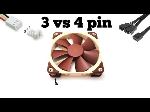 You are after a 3-pin connector on the motherboard with the following setup: Signal-12V-Ground. (In this order I believe. You can read signal or CHA_FAN_SPEED on the manual. Mine reads «signal»)).
It’s harder to connect to the motherboard as you may guess. These connectors are small and it’s tough to securely attach your wires to them without a) buying a adapter yourself or b) go Rambo on it and solder the thing.
Have fun!
4
Wire #3 is just a TACH sensor to tell the computer the fan speed (converted to RPM by the computer) and doesn’t need to be hooked up.
The fan in the picture linked is a 12 V, 1.34 A fan. Doing a quick search of the internet, I see that a 9 V battery can supply from 100 mA to hundreds of mA, but not 1340 mA, so you’re going to need a power supply that can supply more current to get this fan moving.
I did some tests on a 12 V fan, and although not in their specifications, I could lower the voltage to about 5.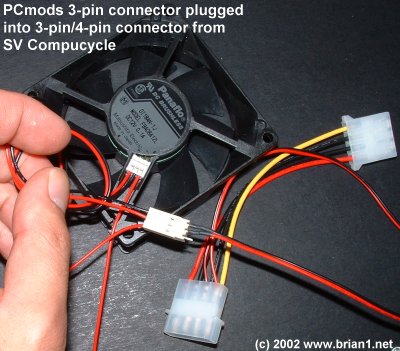 5V before it couldn’t restart when I stopped it with my hand.
Look inside the exhaust port of the fan. You will see a small blue or green thermistor. This controls the speed of the fan. The fan starts slowly and as the air coming out of it warms, the fan will increase in speed. As the air again cools, the fan will slow.
This is done so 1), it makes less noise, and 2), it draws less current when it’s not needed. Pretty nice feature if you want to cool something using a 12 V battery. I use them to cool the heatsink on Peltier modules. As the demand goes up, the fan increases speed and cooling. The red and black wires are + and — 12 volts DC, the white wire is for the tachometer output. You can ignore the white wire if you don’t need feedback from the fan concerning its actual speed.
2
I have this exact same fan, and I had the exact same problem. Sean is right — if you open up the fan (remove the lone screw, then the cover just pops off) you’ll see a little blue or green thermistor.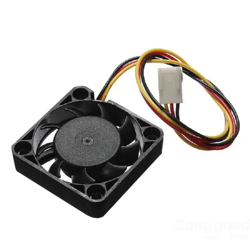 Clip it off, then solder the two pins together — from then on, it’ll run full blast 100% of the time.
Sign up or log in
Sign up using Google
Sign up using Facebook
Sign up using Email and Password
Post as a guest
Required, but never shown
Post as a guest
Required, but never shown
By clicking “Post Your Answer”, you agree to our terms of service, privacy policy and cookie policy
What kind of 3 pin fan connector is this, and where can I buy one?
Ask Question
Asked
Modified
5 years, 2 months ago
Viewed
9k times
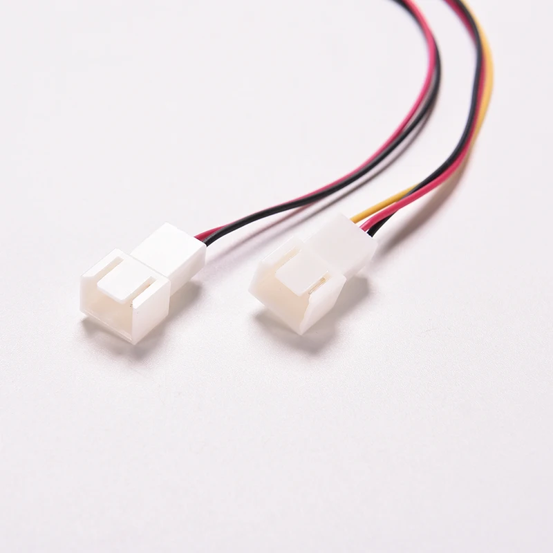
I have a Cyberpower UPS with a very noisy 80mm fan, so I want to replace the fan with a quieter one. I bought a well-reviewed fan from Noctua, but the 3 pin connector doesn’t quite fit. I didn’t realize there were two standards for 3 pin fan connectors. So what is this connector called, and where can I buy an adapter or a fan that uses it?
The original fan from Cyberpower is labeled PSAD18025BH, and spec sheet is here:
http://www.nstech.wtools.com.tw/PDF/ns26_PS8025.pdf
The connector with the yellow glue is from Cyberpower, the other one is Noctua.
EDIT: I realized the two connectors don’t have the same pinout. Standard order is gnd, +12v, tachometer.
This connector order is gnd, RD signal, +12v.
Before I physically mod anything, I’d like to know what happens if I swap the RD and hot wires, shave off the plastic, and plug this in. Apparently RD signals when the motor is locked, but a tach should do a similar thing by reporting 0rpm…?
- fan
- connector
1
That’s a JST XH 2.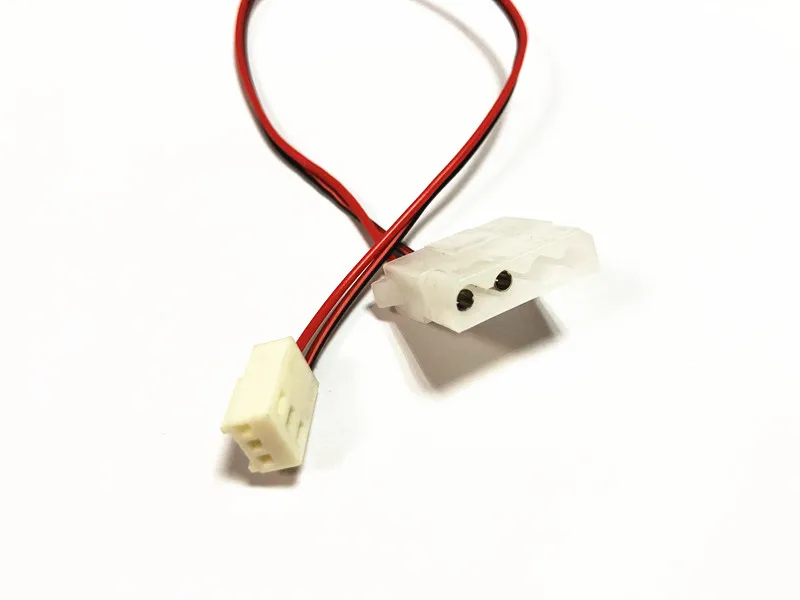 5mm connector. Digikey 455-2219-ND, pins are Digikey 455-1135-1-ND. You can crimp it with an Engineer PA-09 hand crimper. I just had to solve the same issue replacing a power supply fan.
1
It might make sense to simply, very carefully disengage the pins with a needle, then swap the wires to use the existing connectors, or to cut and solder together wires as needed with some heatshrink over it.
From memory, I’ve seen a similar connector in a fan inside a power supply, and it had significantly thicker cables and the fan that you have linked the datasheet for has a higher input power rating than a random noctua fan I looked up. This worries me.
I can’t find any literature on the potential risks of running a fan on slightly higher than recommended current, but if you’re doing this I would keep an eye on the cables connecting the fan to the system to make sure they don’t overheat, and you may experience slightly shorter lifespan due to this. It may be nothing, and no one’s mentioned replacing PSU fans with a regular fan being dangerous in this question.
1
Well, if the wires match (+, — and sense) I would just use some sand paper or sharp knife to adapt the connector for it.
0
Sign up or log in
Sign up using Google
Sign up using Facebook
Sign up using Email and Password
Post as a guest
Required, but never shown
Post as a guest
Required, but never shown
By clicking “Post Your Answer”, you agree to our terms of service, privacy policy and cookie policy
Difference between 4 pin and 3 pin fans — Userello
PC
Author Roman Kolotravov Reading 2 min Views 9.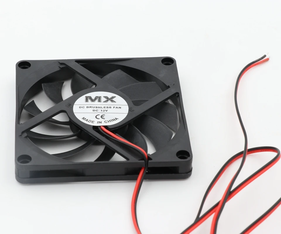 8k. Posted by
What’s Interesting in This Article:
- Key Differences Between 4 Pin vs. 3 Pin Fans
- 3-Wire vs. 4-Wire Connectors
- 3 pin fan connected to 4 pin12 connected to 4 pin connector:
If you have even little experience in assembling computer system units, then you probably noticed that sometimes CPU cooling fan connectors, case fans have a different number of legs: 4 or 3. They are also called 4 pin and 3 pins respectively.
In relatively old system units on motherboards, only the processor fan has 4 wires, while the rest of the connectors have 3 pins.
On modern motherboards based on the sixth or seventh generation of intel processors, as a rule, only 4 pin connectors are soldered, and 3 pin connectors are already living out their short life, and we will no longer see them in the next generations of coolers and fans.
Speaking of 7th generation Intel processors, I advise you to look at the article 👉 Seven things you need to know about 7th generation Intel processors
What is the difference between three and four wired fans, besides the difference in the number of wires? Read the answer to this question later in this article.
The three-pin fan connector is three indicators (by number of wires): power (5 or 12 volts), ground and signal . The signal wire transmits the speed of rotation of the fan impeller at the normal nominal voltage of 4 or 12 volts. In this mode, the fan speed is usually controlled by increasing or decreasing the voltage on the power cable.
The four pin fan connector is slightly different from the three pin connector because it has an extra (fourth) wire used to send control signals to the fan that has the chip. The chip controls the rotation speed of the fan impeller.
3-wire and 4-wire connectors
CPU fans mounted on a copper or aluminum heatsink (collectively, the cooler) use either a 3-wire or 4-wire connector. Three-wire connectors are designed for small fans with low power consumption. The 4-wire headers are for CPU fans with higher power consumption.
3 pin fan connected to 4 pin connector cooler revs.
4 pin fan connected to 4 pin connector
If suddenly the fan does not work, then you need to swap wires 3 and 4 so that the wire with speed control remains unused.
How to connect 2 pin fan to 3 pin?
Hello everyone! Today I will tell you how to connect a 2 pin fan to a 3 pin connector on the motherboard and is it possible in principle. We will also discuss how to power the cooler from the power supply, what needs to be redone and for what exactly.
3-pin slot on motherboard
First, a little about the connectors that you can find on the motherboard. The main one, which is on any motherboard, is marked CPU FAN and is always used to connect a processor cooler. Without such cooling, the CPU will quickly overheat and the computer will crash.
Depending on the model, there may be other connectors on the motherboard from which case coolers can be powered (as an option, you can connect the case cooler to the PC power supply, which is usually what manufacturers are guided by).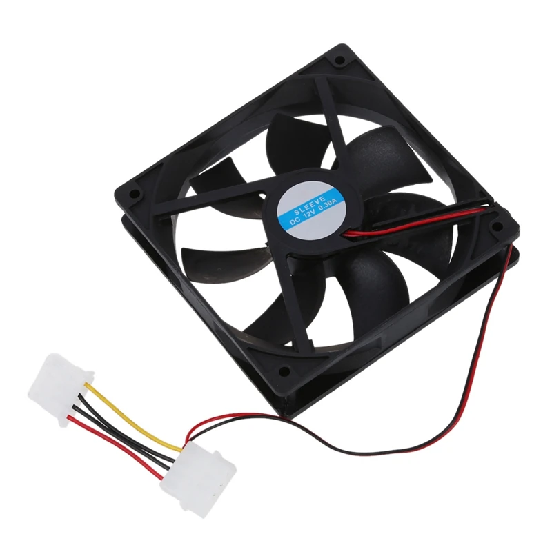 Typically, these connectors are labeled SYS FAN.
The difference between 2 and 3 pin impellers is the presence of an additional cable.
In any case, there is a black cable («ground») and a red one (voltage +12 V). The third wire, which is always marked yellow, is for monitoring the rotation speed of the impeller blades.
However, not all fans have this design feature — many of them, especially budget models, lack the necessary sensor and additional yellow cable. Similarly, on the motherboard, depending on the brand and model, there may be additional power slots from 2 to 4 pins.
Accordingly, if you connect a two-pin impeller, then you will not be able to monitor its rotation speed.
Now I’ll tell you how you can «shovel» the adapter with your own hands. You will need a non-working 3-pin fan, from which you will take a connector with small pieces of wire. Next, you need to solder them by cutting off the old connector at the cooler: black to black, red to red. And don’t forget isolation!
The option is suitable if you need to immediately connect the cooler. But it is better to read the post to the end (and you may not have to solder).
In general, in any store you can find, choose and buy a new cooler for 3 contacts (the price tags are still not high).
How to connect a 3 pin fan to a 2 pin in the power supply
In modern power supplies, 2-pin connectors have not been provided for a long time (you can meet, most often in old ones). Instead, they can even be equipped with a 4-pin connector.
But we can have a fan with a 3pin connector or even with a wire branch to the Molex connector, which in our case is not suitable (but they are very common). What to do?
- If you just have a 3-pin connector, then the 3rd wire is insulated, the first 2 connectors (red and black, most often) are pulled out of the plastic latch and put in place of where the contacts were from the previous cooler (which was in the PSU).