PWM vs. DC vs. Auto Fan Modes for System & Case Fans
TABLE OF CONTENTS
1
If you’ve ever gone rummaging through your BIOS, you might have stumbled across the terms PWM, DC, and Auto in the fan control section.
In this article, I’ll go over PWM vs. DC mode fans and what modes to use for effective cooling and low noise levels.
PWM vs. DC vs. Auto Fan Modes
The Short Answer – DC or PWM Mode?
Before getting started on the explanation, I’ll condense it down for those who want a quick answer.
If you have a 3-pin fan connector, pick DC mode. On the other hand, if you have a 4-pin fan connector, select PWM mode.
If your motherboard fan header only has 3 pins, pick DC regardless of whether you have a 4-pin PWM or 3-pin DC fan.
If you want to find out more about these mysterious terms, read on!
What is PWM and How Does it Work?
PWM (Pulse Width Modulation) fans allow motherboards to control fan speeds using rapid power pulses (on-off cycles). Simply put, a PWM fan turns off and on very fast to run at lower speeds.
This type of fan requires a 4-pin fan connector like the one shown below:
As you can see in the PWM fan pin diagram above, the 4th pin (blue) allows the motherboard to send a PWM signal to the fan, which controls its speed.
Steady pulses of power are used to vary fan speeds in PWM mode, which means that the fan motor switches from the ON to OFF state and back to ON rapidly.
However, the voltage (12V) applied to a PWM fan won’t change regardless of fan speed when in this mode.
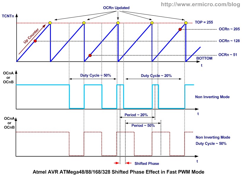
So, the power delivery graph for a PWM fan looks something like this (called a square wave or pulse wave) –
See those power upticks (camel humps) on every duty cycle? Those are pulses that keep the fan speed to what’s needed by a system.
So, a 10% fan speed effectively means that a fan is ‘on’ only for 10% of the total time it’s running.
Thanks to this behavior, PWM fans can typically achieve much lower speeds than their DC counterparts while lowering power consumption in the process.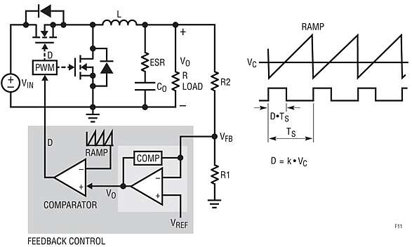
Note – Some premium PWM fans can also contain components that will ‘smoothen’ out this square signal a bit, giving it an upward and/or downward slant each time a pulse is detected.
What are DC Fans? How do they Work?
DC (Direct Current) fans are a bit different. For one, they come equipped with a 3-pin connector like this one:
As you can see, the 4th pinout is missing on DC fans.
While PWM fans rely on sending the same voltage (12V) through a fan but turn the power ‘on and off’ rapidly to achieve lower speeds, DC fans can only change speeds by varying the voltage applied to it.
This means that a DC fan will run at full speed when a voltage of 12V is applied to it but will slow down when this voltage is only, say, 7V.
That said, these fans are still limited by a minimum threshold voltage needed to keep the fan spinning, which limits the minimum speeds they can achieve.
For example, here’s a graph that illustrates how a DC fan’s speed (in %) varies with applied voltage:
Well, what about the AUTO mode?
Picking AUTO will leave the choice up to your motherboard to detect and deliver the correct kind of power to a fan.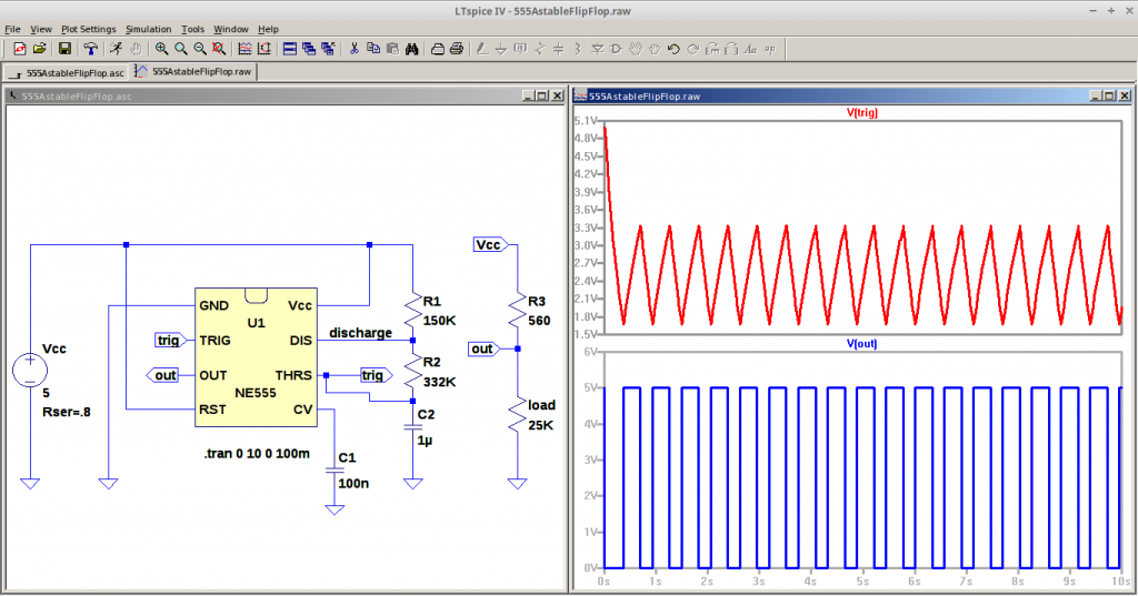
However, this automatic choice CAN be wrong, so if you’re noticing any strange fan speed behavior, go ahead and change it manually.
What Mode to Pick – DC or PWM?
Now, the above section has probably given you a clue about what happens when picking the wrong mode for a fan.
If you have a DC fan, and you’ve selected PWM mode on that fan header, the fan will ALWAYS receive a voltage of 12V. It just doesn’t have that 4th pin to recognize or control pulses, and you end up with a fan that works at 100% all the time.
If you’ve noticed your PC fans spin at full speed on startup before quieting down, this is why – on some boards (mostly older ones), there’s a short delay on waking from a cold start when a full 12V is applied to the fan header before settling into PWM mode. This is one reason for that annoying ‘rev’ when your PC boots up.
Now, on the flip side, what happens if you pick DC mode for a 4-pin PWM fan? Well, nothing very interesting. It just ends up working as a regular DC fan.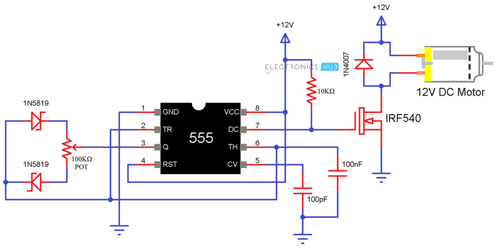 You will be limited to a certain minimum speed, but other than that, it’ll work just fine.
PWM vs. DC Fan Noise
PWM fans will generally be quieter than DC fans because sometimes you’ll hear more electrical noise in some motors when they operate below a specific voltage.
Moreover, as I said above, PWM fans can achieve much lower speeds, which again helps with the noise.
DC fans are cheaper to manufacture, and you’ll see them extensively used in systems that are meant to keep fans at a full 100% speed.
Servers are a great example here.
CGDirector is Reader-supported. When you buy through our links, we may earn an affiliate commission.
Which Is Better to Cool Your PC?
Computers generate a lot of heat, but excessive heat can cause damage to the internal components of your PC. Fans are a vital part of your PC that helps minimize this heat and keep your computer running stable.
If you’ve ever built a PC or dug into your BIOS, you might’ve come across the terms DC and PWM — the two primary types of fans in a computer.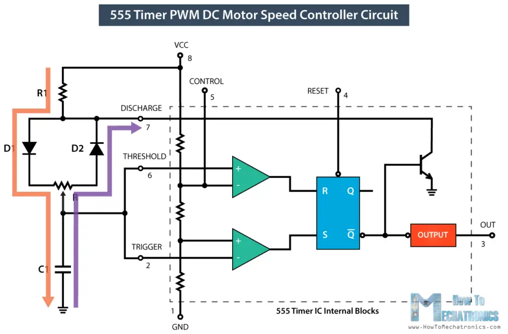 So, what are they? Here, we’ll look at the differences and determine which fan is better for your needs.
What are DC and PWM Fans?
Direct Current (DC) and Pulse Width Modulation (PWM) fans are the two main types found in computers. These fans differ in crucial ways that change how you use them in a computer.
What’s a DC Fan?
A DC fan is a traditional computer fan. They run on a fixed voltage from a DC power supply or via the motherboard and provide consistent cooling to your computer.
DC fans have 3-pin connectors: A power supply pin, a ground pin, and a signal pin. The signal pin collects information about how fast the fan is spinning (called tachometer output) and alerts if the fan stops working.
The most common voltage for DC fans is 12V, though they also come in 5V, 24V, and 48V. The higher the voltage, the quicker the fan speed, and the greater the cooling. This means that you can lower the fan speed by reducing the voltage, though most fans will stall below a certain speed.
Some DC fans now come with a voltage controller built-in, though it’s also possible to alter the voltage through the BIOS or with a third-party fan controller.
Read More: The Best PC Fan Controllers
What’s a PWM Fan?
PWM fans are very similar to DC fans but differ in one key aspect: They have an extra pin for pulse width modulation. This fourth pin takes input from the motherboard to directly control the fan’s speed.
PWM fans work via repeated pulses of power. Essentially, PWM fans are either ON or OFF and can be switched from one to the other rapidly to control the overall fan speed. This pulsing is called a duty cycle. A 40% duty cycle, for example, means that for one entire cycle, the fan is only running for 40% of the time.
The motherboard controls the speed of PWM fans according to temperature readings from various parts of the PC, but primarily the CPU. In addition, the way that PWM fans are controlled means that they can achieve much lower speeds than DC fans.
DC vs. PWM Fans: Key Differences
Despite being very similar, the differences between DC and PWM fans may make them better for different applications. However, keep in mind that there are many more important aspects to consider when choosing the best case fan for you.
Related: How to Choose the Best Case Fans for Your Custom PC
Number of Pins
DC fans have three pins:
- 12V power supply pin
- Grounding pin
- Tachometer pin
PWM fans have four pins:
- 12V power supply pin
- Grounding pin
- Tachometer pin
- PWM pin
Fan Speed Control
DC fan speed is adjustable by limiting the voltage supplied to the pin. In contrast, PWM fan speed is controlled by precisely turning the fan motor on and off during duty cycles. DC speed control isn’t as refined as PWM, but this aspect doesn’t take much from its effectiveness, especially in the latest models.
Essentially, you have far more control over PWM fan speed, though it’s becoming more common to see DC fans with control knobs.
Minimum Fan Speed
Since the DC fan is slowed by reducing its voltage, it can stall below a certain voltage threshold. This occurs when there isn’t enough power supply to keep the fan moving. With PWM fans, you can achieve a much lower fan speed by reducing the duty cycle.
Another bonus is that PWM fans will never stall since their entire function is to turn on and off repetitively.
Noise
A side-effect of the greater speed control that PWM fans provide is that while the computer doesn’t need the extra cooling, it will spin far slower and produce far less noise than DC fans. Since DC fans typically run faster than PWM fans while idling, they are louder.
Another thing to remember is that some DC models will generate electrical noise (one of those strange PC noises that occasionally arise) while they aren’t operating at 12V. Since PWM fans always run at 12V, this isn’t an issue.
However, differences in the noise level will be minuscule during peak PC performance. The main thing that determines the noisiness is the fan’s maximum RPM and its overall build quality.
Cost
DC fans generally cost less than their PWM cousins since they’re cheaper to produce. So, if the price is the main deciding factor for you, DC is easily the better choice.
Power Consumption
Due to the way PWM fans function, they’re generally more efficient than DC fans and use less power. Consider the duty cycles of PWM fans. When a fan is on a 40% duty cycle, it’s only using electrical power 40% of the time. In comparison, the DC fans, if anything, will use a slightly lower voltage.
Primary Uses
DC fans are more commonly used as case fans or in situations where the system is likely to need to maintain 100% fan speed, such as in the case of a 24/7 server. PWM fans are more valuable if noise is a significant concern or if you’re looking for maximum power efficiency in your setup.
Which Fan Is Better?
Over the years, technology has improved to the point that there aren’t many reasons to prefer one over the other for the average person.
PWM fans will usually set you back more, but use less power and produce less noise. DC fans are likely just as effective and cheaper, but they will also be noisier.
One thing to consider is the number of 4-pin connectors on your motherboard. If you have plenty, you may want to stock up on PWM fans, as these are slightly more effective. However, if you’re looking for case fans (and noise isn’t an issue), there’s no reason not to go with the cheaper DC fans.
What is PWM — How Pulse Width Modulation works
Contents
- 1 What is PWM (Pulse Width Modulation)?
- 1.1 Scope
- 2 shim controller: principle of operation
- 2.1 Analog SHIM
- 2.2 Digital SHIM
- 3 Principle of ShIM-regulator
- 3.1 Example of the SHIM regulator
- 4 The difference between the between shim and shir?
9000 9000
Microprocessors work exclusively with digital signals: logic zero (0V) or logic one (5V or 3.
 3V). For this reason, the microprocessor cannot form an intermediate voltage at the output. The use of external DACs for solving such problems is impractical because of the complexity. Especially for this, pulse-width modulation was developed — a certain process of controlling the power going to the load by changing the duty cycle of pulses of constant frequency. nine0003
 What is PWM (Pulse Width Modulation)?
This is a modern method of controlling the level of power supplied to the load, which consists in changing the duration of the pulse at a constant repetition rate. This is a signal modulation technology due to the variable change in the width of the pulses, and not the output voltage. PWM converter can be analog, digital, etc.
Pulse width modulation — the most important parameters:
- T -clocking period — time intervals at which pulses are applied. nine0008
- Pulse duration — time until the signal is applied.
- Duty cycle — the ratio of the pulse length to the pulse T clock period calculated by the formula.

- D duty cycle — inverse duty cycle.
Scope
The use of PWM allows you to increase the efficiency of electrical converters. Moreover, this applies to pulse converters, which today are mainly used in secondary power supplies of various electronic devices. Pulse converters are flyback, forward 1-stroke, 2-stroke, half-bridge, resonant controlled with PWM. nine0003
The PWM principle has now become the main principle for electronic devices that require the maintenance of output parameters at a given level and their regulation. The method is used to change the speed of rotation of engines, the brightness of light, control the power transistor of a pulse-type power supply unit.
PWM modulation is also used in LED brightness control systems. The LED, due to its low inertia, has time to blink at a frequency of only a few tens of kHz. For the human eye, the operation of an LED in a pulsed mode is perceived as a glow. The brightness of the LED depends on the duration of the pulse during one cycle.
 With a duty cycle of 50%, that is, if the glow time is equal to the pause time, the brightness of the LED is one half of the nominal value. When 220V LED lamps appeared, there was a problem of increasing their reliability with an unstable input voltage. The problem was solved by the development of a power driver operating on the PWM principle. nine0003
 The spread of devices operating on the PWM principle made it possible to move away from linear transformer power supplies. As a result, the efficiency increased and the weight and dimensions of the power sources decreased. Therefore, today the PWM controller is today an integral part of the switching power supply. It controls the power transistor and the voltage at the output of the power supply always remains stable. In addition, the PWM controller:
- provides a smooth start of the converter;
- limits the duty cycle and the amplitude of the control pulses; nine0008
- monitors the input voltage;
- protects against short circuit of the power key;
- puts the device into standby in an emergency.
 mode.
mode.
Today, pulse-width modulation is used everywhere and allows you to control the brightness of the LCD backlight of mobile phones, smartphones, laptops. A PWM chip has been implemented in welding machines, in auto-inverters, in chargers, etc. PWM is used in any charger today.
PWM controller: how it works
The PWM signal is controlled by the PWM controller. It controls the power key due to changes in control pulses. In the key mode, the transistor can be fully open or fully open. In the closed state, a current of no more than a few μA flows through the p-n junction, that is, the dissipation power is close to zero. In the open state, a large current flows, but since the resistance of the p-n junction is small, small heat losses occur. More heat is released during the transition from one state to another. However, due to the speed of the transient compared to the modulation frequency, the power of these losses is negligible. nine0003
All this made it possible to develop a highly efficient compact pulse-width converter, that is, with low heat losses.
 Resonance converters with switching to 0 current ZCS allow to reduce heat losses to a minimum.
 Analog PWM
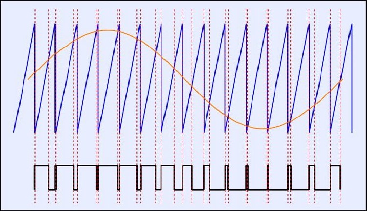
In analog PWM generators, the control signal is generated using an analog comparator, when a sawtooth or triangle signal is applied to its inverting input, and a continuous modulating signal is applied to its non-inverting input. nine0003
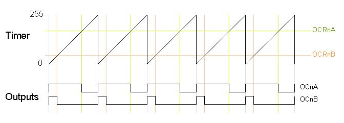
The output pulses are square wave. The frequency of their repetition corresponds to the frequency of the saw, and the duration of the positive part of the pulse depends on the time when the level of the constant modulating signal going to the non-inverting input of the comparator is higher than the level of the sawtooth signal supplied to the inverting input. During the period when the voltage of the sawtooth signal exceeds the modulating signal, the negative part of the pulse will be fixed at the output.
When the sawtooth signal is applied to the non-inverting input and the modulating signal to the inverting input, the output square wave will be positive when the sawtooth voltage is higher than the modulating signal level at the inverting input, and negative when the sawtooth voltage is lower than the modulating signal.
 nine0003
 Digital PWM
Working with digital information, the microcontroller can generate either 100% high or 0% low voltage levels at the outputs. But for effective load control, this output voltage must be changed. For example, when adjusting the speed of rotation of the motor shaft or when changing the brightness of the LED.
PWM controllers solve the problem. That is, a 2-level pulse-coded modulation is a series of pulses characterized by a frequency of 1/T and either a width T or a width 0. Oversampling is applied to average them. With digital PWM, rectangular subpulses, which fill the period, can occupy any place in the period. Then only their number affects the average value of the signal for the period. Since the process is carried out at a frequency of hundreds of kHz, smooth adjustment can be achieved. PWM controllers solve this problem. nine0003
We can draw the following analogy with mechanics. When the flywheel is rotated by the motor, when the motor is turned on, the flywheel will spin up or continue to rotate, if the motor is turned off, the flywheel will brake due to frictional forces.
 However, if the engine is turned on/off for a few seconds, the flywheel will keep rotating at a certain speed due to inertia. The longer the engine on period, the faster the flywheel spins. The PWM modulator works the same way. This is how PWM controllers work, in which switching occurs thousands of times per second, and frequencies can reach units of megahertz. nine0003
 The use of PWM controllers is due to their following advantages:
- stability;
- high signal conversion efficiency;
- energy saving;
- low cost.
You can get a PWM signal on the microcontroller (MK) outputs:
- by hardware;
- programmatically.
Each MCU has a built-in timer that generates PWM pulses on certain pins. This is the hardware way. Getting a PWM signal using programming commands is more efficient at the expense of resolution and makes it possible to use more pins. But the software method causes a high load on the MK, taking up a lot of memory.
 nine0003
 The principle of the PWM controller
The operation of the PWM controller is not difficult. A PWM regulator is a device that performs the same function as a traditional linear power regulator (that is, it changes the voltage or current due to a power transistor that dissipates significant power on itself). But the PWM controller is much more efficient. This is achieved due to the fact that the control power transistor operates in the key mode (either on, then it passes a large current, but there is little voltage drop, or it is turned off — the current does not pass). As a result, there is practically no power dissipation on such power transistors and no energy is wasted. nine0003
After the power transistor, the voltage comes out as rectangular pulses with a varying duty cycle depending on the required power. But the signal needs to be demodulated (that is, to highlight the average voltage). This process occurs either in the load itself (when it is of an inductive nature) or if a low-pass filter is placed between the load and the power stage.
An example of using a PWM regulator
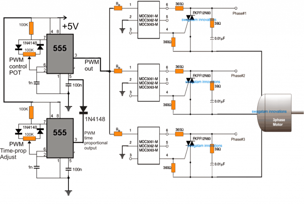
The simplest example of using a PWM voltage regulator is the NE555 PWM chip, which every radio amateur is familiar with. Due to its versatility, it is possible to design a wide variety of parts: from the simplest pulse single vibrator with 2 in the strapping to a modulator consisting of a large number of components. The PWM voltage regulator has a wide range of applications — these are circuits for adjusting the brightness of LEDs and tapes, as well as adjusting the speed of rotation of engines. nine0003
What is the difference between shim and shir?
In the West, the concepts of pulse-width regulation of PWM and PWM practically do not differ. However, we still have a difference between them. Many microcircuits implement the PWM principle, but they are still called PWM controllers. Thus, there are practically no differences in the name of these two methods.
The only difference between PWM and PWM is that with PWM, the pulse and pause times are constant.
 And with PWM, their durations change, which allows you to generate an output PWM signal of a given shape. nine0003
 What is PWM and why does OLED flicker? DESCRIBE / Sudo Null IT News
PWM, everyone around is talking about PWM. Well, who knows — I don’t see him. What do you mean, if I lower the brightness of the display, will it somehow tire me? Looks like there’s something here!
Today we will explain how PWM actually works. Let’s find out how many FPS a person sees, and how many a fly. Let’s carry out PWM tests on an oscilloscope. And, of course, we will tell you how to get rid of PWM on Samsung and iPhone.
OLED displays have actually surpassed IPS in every way. But some people simply cannot physically use OLED, because they feel tired eyes, dryness and even headaches. nine0003
Why is that? The fact is that, unlike most IPS screens, most OLED matrices flicker. About the same as cheap fluorescent lamps. And it’s not good for eyesight.
But stop! Personally, I don’t have any problems with OLED displays, and my friends go with OLEDs and don’t complain.
Indeed, according to statistics, the majority (approximately 90%) of people do not experience the flicker of OLED displays. We even conducted a survey: Do your eyes get tired of OLED displays? Do your eyes get tired from IPS displays? And we got the following results: about a quarter — 27% reported that their eyes get tired. A minority, but still a quarter! nine0003
However, there are people who not only feel the PWM, but even see it clearly. How does it work?
PWM in movie projectors
To answer this question, let’s talk about cinema. Old movie projectors, which still had film reels, played movies at 24 frames per second.
So, in order for the image not to be smeared when changing frames and you do not see the moment of rewinding the film, at this moment the light flow was blocked. This led to hellish flicker, as the image was constantly interrupted by a “black frame”.
 nine0003
 Since it was not technically possible to speed up the process of changing frames, filmmakers came up with another hack. They began to overlap the image twice: not only during a frame change, but also when a static frame was displayed on the screen. Mmm. And what’s the point?
This alternation of the image and additional «black frames» made it possible to artificially increase the flicker frequency up to 48 times per second. Which was enough to fool the brain. Seeing a constantly flickering picture, the brain simply “turns off” the perception of flicker and we see a smooth picture. By the way, in silent movies, where a frequency of 16 K / s was used, they generally overlapped 3 times and flickered — 48 times per second. nine0003
How many frames do we see?
This incredible effect of human vision is called flicker fusion threshold and this threshold is 60 Hz. This means that everything that flickers more than 60 times per second will be perceived by a person as a continuous image.
By the way, in dogs and cats this threshold is higher — in the region of 70-80 Hz, and in flies it is generally 250-300 Hz.
What is it, gaming monitors 144 Hz and above — is it all marketing? No, 60 frames per second is the minimum threshold at which a person stops seeing flicker. nine0150
And people with trained eyesight, for example, fighter pilots, in testing distinguish frames that appear at 4 ms. Which corresponds to 250 frames per second. This also applies to hardcore gamers.In fact, there are studies where people were able to distinguish between 480 fps and even more in some conditions.
But in general, according to GOSTs: Illumination ripple over 300 Hz does not affect the general and visual performance. GOST R 54945-2012
Why is PWM needed? nine0149
So, we figured out the vision. But why do OLED displays flicker at all and at what frequency?
Let’s first answer the question «Why?»
There are two ways to adjust the brightness of the display:
The first and most obvious way is by lowering the voltage.
 The less we apply energy to the display, the less it glows.
 This is how the brightness is adjusted in most IPS displays in our smartphones, laptops and monitors.
But why not do the same with OLED displays? In fact, it is possible, and it has even been done before. For example, the LG G Flex 2 smartphone used just such an approach. But there’s a problem! On OLED displays, when the voltage decreases, the picture suffers greatly. There is a so-called Mura effect, better known as the “sandpaper” effect. We talked about this in detail in the article about OLED. nine0003
Therefore, to avoid such image degradation, a second approach is used: dimming with flicker or PWM. PWM stands for Pulse Width Modulation, or PWM in English. This literally means — adjusting the width, well, or duration, of the pulse.
So wait, what’s that impulse? The fact is that the voltage in displays using PWM is not constant, but intermittent. It is delivered with the help of such bursts or impulses.
The number of pulses per second is called frequency and is measured in Hz. And the time that each cycle of pulsation takes is called a period. nine0003
For example, take a frequency of 250 Hz, in this case the period will be 4 ms. The frequency and period are fixed values and do not change with the brightness of the display. But the width of each pulse is just what we can adjust. This value is called duty cycle and is expressed as a percentage.
If the duty cycle is 100%, the pulse will last 100% of its period, i.e. 4 ms. This corresponds to 100% display brightness. If we reduce the pulse width to 50% or 2ms, the perceived brightness of the display will also drop to 50%. And at a brightness of 1%, actually 99% will display just a black screen, but our vision interprets this as just a very dim picture. It turns out that the lower the brightness of the display, the more pronounced the flickering effect. And the worse it is for the eyes.
PWM frequency in different displays
In fact, PWM is used not only in OLED displays, but also in IPS.
 But unlike OLED, IPS screens use a very high flicker frequency, over 2000 Hz. Naturally, neither a man nor a fly can notice such a fast flicker. And that means the eyes will not get tired. nine0003
 What is the PWM frequency in OLED?
It all depends on the specific model, but there are certain patterns. First, it is desirable that the PWM frequency be a multiple of the display refresh rate. Therefore, on 60 Hz or 120 Hz displays, as a rule, the PWM frequency is 240 Hz, and on 90 Hz displays, 360 Hz.
We decided to see for ourselves and went to St. Petersburg. There, the guys from the LLS company prepared for us an oscilloscope with a high-speed photodetector.
This is how we tested for PWM on the iPhone 11 Pro and Pixel 4.
Tests showed that the iPhone 11 Pro, contrary to popular belief, flickers a little even at maximum brightness, at 240 Hz. By reducing the brightness to 50%, the flickering becomes less pronounced, which means that the voltage reduction is used on the iPhone up to this point.
 Well, then PWM enters the battle. On the oscilloscope, it is very clearly visible how, as the brightness decreases, the pulse width decreases, which means that the flicker increases.
 In Pixel 4, up to 70% brightness, we did not detect PWM at all, only screen update is visible 90 Hz. And then PWM starts at a frequency of 360 Hz. But since the Pixel 4 refresh rate drops to 60Hz after 40%, you can see how every fourth pulse jumps a little. This is because the refresh rate is not the same as the modulation rate.
You can check the PWM frequency for other models on notebookcheck.net. However, some measurements there look doubtful. Or on our native IXBT.com, everything is ok with tests there.
- Galaxy S20 — 242.7Hz
nine0005 Galaxy S20 Ultra — 240.4 Hz
- Google Pixel 2 — 245.1Hz
- Google Pixel 2 XL — 242.7Hz
- Google Pixel 3a — 271.1Hz
- Google Pixel 3a XL — 242.7Hz
- Google Pixel 4 — 367.6Hz
- Google Pixel 4 XL — 367.
 6Hz
6Hz - Huawei P30 — 240.4 Hz
- Huawei P30 Pro — 231.5 Hz
- Huawei P40 — 245 Hz
- Huawei P40 Pro — 365 Hz
- iPhone 11 Pro — 290.7 Hz
- iPhone 11 Pro Max — 245.1Hz
- iPhone XS — 240.4 Hz
- iPhone XS Max — 240.4Hz
- OnePlus 5T — 242.7Hz
- OnePlus 6T — 240Hz
- OnePlus 7 — 200Hz
- OnePlus 7 Pro — 122Hz
- OnePlus 7T Pro — 294Hz
- OnePlus 8 Pro — 258Hz
- Samsung Galaxy A50 — 119 Hz
- Samsung Galaxy A51 — 242.7 Hz
- Samsung Galaxy A71 — 247.5 Hz
- Samsung Galaxy S10e — 232 Hz
- Xiaomi Mi 10 — 362.3 Hz
- Xiaomi Mi 8 — 238 Hz
- Xiaomi Mi 8 Explorer Edition — 100 Hz
OnePlus 7 Pro:
Samsung Galaxy A50:
In fact, the flicker frequency of OLED displays can be increased, if not up to 2000 Hz, but at least up to 500 Hz. By the way, this was the PWM frequency in the ancient Windows Phone — Lumia 950. But this increases the cost of production, and since there are few suffering people, manufacturers are not ready to steal from their own pockets. nine0003
By the way, almost all modern LCD TVs also PWM at 240 Hz. And in telly this effect is even more noticeable than in phones.
Except that SONY were not stingy to install brightness controllers in their LCD models either without flickering or with flickering at a frequency of 720 Hz.
How to check the PWM yourself?
But how do you test the PWM on your phone, laptop or TV by yourself? If you do not have an oscilloscope with a high-speed silicon photodetector at hand. nine0003
Really very easy! You need to capture the screen in slow motion video at 240 fps or more. Now almost any phone can do this. If at all brightness values you will not see flicker in the form of moving bands. So there is no SHIM.
What is DC Dimming?
Nevertheless, there is a problem and Xiaomi was the first to realize it, introducing the DC Dimming function in the Black Shark 2 Pro. This topic has gone so well that OnePlus, OPPO and Huawei have been in a hurry very quickly. And since last year, all flagships definitely have DC Dimming. nine0003
The name itself stands for Direct Current Dimming, which translates as direct current dimming. In other words, in this case, the brightness is regulated as it should be by lowering the voltage.
STOP! But also impossible! The picture will die! In fact, this could not be done before, because the quality of OLED displays left much to be desired. But now everything is different.
For a long time, many manufacturers have been using a hybrid way of dimming. For example, on the iPhone, up to 50% brightness, voltage reduction is used, and only then PWM is turned on. And phones with the DC Dimming function went further and began to regulate the brightness exclusively by lowering the voltage. nine0003
Yes, turning DC Dimming on at low brightness may cause some color shifting and noise. But this is not critical at all.
And tests show that the function actually works. Although brightness fluctuations are not completely smoothed out, this approach still allows us to significantly reduce the load on our eyes.
According to our measurements on Xiaomi Mi 10, PWM with DC Dimming enabled disappears completely! So your eyes can rest.
Remove PWM for all
But what if you didn’t get DC Dimming? For example, do you have a Samsung that PWMs even at 100% brightness, or an iPhone that starts PWMing at 50%?
In fact, there is a solution and it is software. Its name is screen filters!
Android. For example, on any Android, you can install the OLED Saver program. She can apply a semi-transparent gray filter over the entire image. By adjusting the transparency of the filter, the brightness is adjusted. This program can simulate the auto-brightness function. You can quickly adjust the transparency of the filter from the curtain and set up autorun after a reboot. nine0003
I can’t say it’s very convenient. But it can be very useful if you like to stick to your phone before going to bed in the dark.
iPhone. And the iPhone generally has a special mode built into the system. It’s called «White Point Lowering» and is hidden in the «Accessibility» section. The path is this: Settings> Accessibility> Display and text size> Lowering the white point
0336 Settings > Accessibility > Shortcut.
In iOS 14, you can even assign the same to tapping on the back cover. But I would not recommend doing this, there will be false positives.
And finally, you can bring a shortcut with this function to the control center. To do this, go to Settings > Control Center and drag the «Commands for accessibility» icon.
Results
What is the result? PWM is, of course, evil.