Where do you Connect Your AIO Pump on your Motherboard?
TABLE OF CONTENTS
1
You did it. You finally caved in and bought a liquid cooler—if for nothing else than to shut up that one annoying friend that keeps bugging you to get liquid cooling.
And now that it’s finally here and…
How exactly are you supposed to use it without frying your CPU?
The NZXT Kraken x63 280mm AIO RGB CPU Liquid Cooler – Image-Credit: NZXT
Well, let’s get some short questions out of the way real quick so we’re on the same page before diving into the main topic of this Article: How to connect your AIO properly!
What does AIO stand for?
What is an AIO, anyway?
Well, AIO stands for “All In One,” and in PC cooling describes a liquid Cooler that is ready to be used without the need for custom tubing or liquid setup. It’s plug-and-play and can be installed more easily than custom liquid cooling.
What Is an AIO Pump?
On most AIO liquid coolers, the pump is the part you place right on top of the CPU.
The pump is responsible for moving the liquid through the radiator and tubing.
When it comes to any liquid cooling setup, the pump is the heart of the system. This is especially true for a closed-loop system.
If your pump is on the fritz, your cooling performance will go down significantly, to the point where the boxed air cooler you get with your CPU would do a better job of cooling it.
So you must ensure that your pump is mounted properly, thermal-paste and all, working well and that it’s not making any weird noises.
Where to Connect Your AIO Pump
Trying to figure out where to connect your AIO pump can get confusing, as there are so many headers for fans on a motherboard.
But it has gotten quite a bit easier these days.
Here’s which cables are usually attached to an entire AIO:
- 3-Pin Connector
- 4-Pin Splitter Connector(s)
- SATA Connector
- (USB Connector)
You’ll find these kinds of schematics in your AIO manual – NZXT
So what are all these cables meant for, and where should they be plugged in?
Let’s see:
3-Pin Connector: The 3-Pin Connector should be plugged into your Motherboard’s CPU_FAN Header. It controls the Pump and Fan speeds on your entire AIO. It also ensures the Motherboard does not show a CPU Fan Error when booting.
4-Pin Splitter Connectors: These are meant to be connected and power all your Radiator Fans and ramp them up or down depending on what CPU Temperature is reported by the Motherboard through the CPU_FAN Header.
SATA-Connector: The SATA-Connector should be plugged into a free SATA cable of your choosing and will power the Pump Motor of your AIO and any RGB, LED-Display, or Tach-Features you might have.
USB-Connector: The USB-Connector should be plugged into a free USB 2.0 Header on your Motherboard and is meant to control your AIO and any RGB Features through Fan-Software.
Fan Header placement on Asus’ Maximus Hero Motherboard
There are a lot of different AIOs on the market. Here’s what Corsair’s h250i Manual says about connecting your AIO:
Here’s the problem:
Because the entire AIO is plugged into the CPU_FAN Header, this also means that both the Pump and Radiator Fans are temperature controlled.
The Pump, though, will be less prone to wear and tear if it runs at a static speed. This is why there is an AIO_PUMP or PUMP_HEADER on many Motherboards. You can plug in your Pump (if it comes with a separate 3-Pin connector) to this Header to control it separately from the radiator’s fans or set it to a fixed 50% to 100% PWM speed.
What if Your Motherboard Doesn’t Have an AIO Pump Fan Header?
Don’t worry; you can still make it work.
If not, here’s a little secret. Those pump-specific headers are all glorified SYS_FAN headers in disguise.
So if your motherboard doesn’t have any AIO_PUMP headers or similar, you can always use SYS_FAN or CHA_FAN as a substitute to plug in your pump if you have a spare one available. It will work the same.
Double-check in your BIOS’s Hardware Monitor, though, that the Header that powers your AIO Pump is set to run at 100% speed.
In Summary
And that was a short article on where you can plug in your shiny new AIO liquid cooler.
If you want a TL;DR on it, the gist of the matter is that you have many options when it comes to where you want to plug in your pump.
You can plug it into an AIO_PUMP header, PUMP_HEADER, W_PUMP, or any other variation of that, and you can even use CPU_FAN or SYS_FAN if you really have to as well.
FAQ
Can you plug an AIO pump into a fan header?
Yes. It will work perfectly fine. You’ll just lose a system fan header.
Can you plug an AIO pump into CPU OPT?
Yes. But it’s really not recommended. CPU_OPT should ideally be saved for the fans that go on your CPU cooler, whether it be liquid or air. That’s because CPU_OPT is a special connection that your motherboard uses to ensure that your CPU is always cool.
It detects whether your CPU is thermal throttling (getting too hot) and increases or decreases the speed of the fans appropriately.
Can a 3-pin fan plug into a 4-pin connector?
Yes. You won’t get the same level of control as with a 4-pin PWM fan, but you can still plug in a 3-pin fan to a 4-pin connector perfectly fine. For more info, check out our PWM vs. DC Fans article.
How can you tell if your liquid cooling Pump is working?
The easiest way to make sure your AIO Pump is working is by touching it with a finger to see if it’s vibrating.
Depending on where you plugged in your Pump you’ll also be able to read your Pump speed in your BIOS or with Monitoring tools such as HWInfo.
Over to you
Hopefully, that explained all your questions about where to plug in your AIO cooler on your motherboard!
Got any other unanswered questions about them? Ask us in the comments or our forum!
CGDirector is Reader-supported. When you buy through our links, we may earn an affiliate commission.
Welchen FAN-Header sollte ich verwenden?
Aktiv
Inaktiv
Functional cookies are absolutely necessary for the functionality of the web shop. These cookies assign a unique random ID to your browser so that your unhindered shopping experience can be guaranteed over several page views.
Aktiv
Inaktiv
Diese Cookies werden verwendet, um anonymisiert Daten für Statistiken und Analysen zu erfassen und darauf basierend unsere Inhalte, die Funktionen unseres Onlineshops sowie Marketingaktivitäten zu optimieren und Werbung und/oder Inhalte in anderen Zusammenhängen, in weiterer Folge zu personalisieren.
Aktiv
Inaktiv
Aktiv
Inaktiv
Aktiv
Inaktiv
Aktiv
Inaktiv
Wir nutzen Cookies, um Dir die bestmögliche Nutzung unserer Webseite zu ermöglichen und unsere Kommunikation mit Dir zu verbessern. Wir berücksichtigen hierbei Deine Präferenzen und verarbeiten Daten für Marketing und Analytics nur, wenn Du uns durch Klicken auf «Alle akzeptieren» Deine Einwilligung gibst oder über den Button „Präferenzen setzen“ eine spezifische Auswahl festlegst. Mehr Informationen
Vacuum pumps Elmo Rietschle VGD, VC
Oil rotary vane vacuum pumps Elmo Rietschle VGD, VC (manufactured in Germany) are used for evacuation of hermetic volumes of air, non-explosive and non-poisonous dry gases, gas-air mixtures or to create a permanent vacuum. The wide model range of the series includes models capable of providing a vacuum of 2.0, 0.5, 0.1 mbar and a capacity from 10 to 300 m3/h. All pumps have a ready-made functional filling — an inlet microfilter, an outlet filter and an oil separator, a check valve and a gas ballast device. nine0003
The quality of Elmo Rietschle pumps is a cut above even compared to other German manufacturers.
The main parts of the pump design are designed and manufactured in Germany. The pump failure rate is close to zero. The price is proportional to the quality.
A bit of history:
The German company Elmo Rietschle is part of the American concern Gardner Denve. It was created in 2006 by the merger of market leaders Elmo and Rietschle. nine0003
Elmo — founded in 1903 in Germany, the company is the founder of vacuum equipment, it owns the development and production of the world’s first liquid ring vacuum pump.
Rietschle — founded in Germany in 1950, this company owns the first development and the first serial production of rotary vane oil-sealed vacuum pumps.
Gardner Denver Schopfheim GmbH (USA) was founded in 1927 and is currently the world market leader in vacuum technology. In 2006, the group acquired Elmo and Rietschle and merged them into one group. nine0003
All pumps are streamlined, reliable and easy to maintain.
VGD — compact and quiet pumps with a capacity of 10 m3/h. Vacuum depth 2/10 mbar, set using a gas ballast device. Oil volume 0.4 l. Noise level 59 dB.
Basic equipment — inlet microfilter, oil separator and outlet exhaust filter, gas ballast device, non-return valve.
VCB — pumps with a capacity of 20 m3/h. Vacuum up to 2 mbar. Oil volume 0.35 l. Noise level 63 dB. nine0003
Basic equipment — microfilter at the inlet, oil separator and exhaust filter at the outlet, non-return valve
VCA — quiet pumps with a capacity of 25 m3/h. Vacuum up to 0.5 mbar. The volume of oil is 1 l. Noise level 57 dB.
Basic equipment — inlet microfilter, oil separator and outlet exhaust filter, gas ballast device, non-return valve.
VC 50-150 — pumps with soundproof casing. Capacity from 50 to 150 m3/h, vacuum depth up to 0.1 mbar, with gas ballast device switched on up to 0.5 mbar. The volume of oil is 3.0-3.5 liters. Noise level 64-68 dB. nine0003
Basic equipment — inlet microfilter, oil separator and outlet exhaust filter, adjustable gas ballast device, check valve.
VC 200-300 Powerful pumps in soundproof housing. Capacity up to 303 m3/h, vacuum depth up to 0.1 mbar, with gas ballast device switched on up to 0.5 mbar. Oil volume 8 l. Noise level 69-70 dB.
Basic equipment — inlet microfilter, oil separator and outlet exhaust filter, adjustable gas ballast device, check valve. nine0003
All models are air-cooled, operating at ambient and suction temperatures from 12 to 40 C.
Micro strainer — protects the pump from dust.
Gas ballast device — allows you to work with steam-air mixtures, eliminates condensate.
Check valve — prevents oil from being sucked into the chamber.
Oil separator — used to return oil to the oil circuit.
Exhaust filter — removes oil from the air. nine0003
Oil consumption varies according to operating conditions.
The pumps are equipped with single-phase and three-phase motors 2850/min, 1450/min, power 0.37 — 5.5 kW.
Standard power supply 220V/380V/50Hz.
All motors are designed for continuous duty (S1).
Complies with DIN EN 60034 and is designed to IP 55 protection and insulation class F.
The electrical data are indicated on the rating plate.
The pump is primed with oil families that meet the requirements of DIN 51506-VDL, ISO 6743-3 DVA and DVC. Viscosity class ISO-VG 100 according to DIN 51519.
Each pump is labeled with recommended oils.
List of original Elmo Rietschle oils:
MULTI-LUBE 100 — mineral oil according to DIN 51506, VC/VCL group.
SUPER-LUBE 100 is a synthetic oil with good hydrolysis resistance, thermal and chemical resistance.
-
Pump
-
Delivery documentation: operating instructions, declaration of conformity. nine0003
-
Related documents: spare parts list, data sheet, manufacturer’s declaration.
Operation and maintenance
Is it necessary to turn off the MSD if it is not used for a long time?
If the mass spectrometer is not used for several days (up to a week), it can be left switched on. If the device will not be used for several months, it is recommended to turn it off. At the same time, it should be borne in mind that the longer the mass spectrometer was in the off state, the longer it takes to enter the mode. For example, if the MSD has been in the off state for several months, then the time to enter the mode may be one day; if several days, it will take several hours to enter the regime.
nine0003
Collapse
What are the most common causes of vacuum deterioration?
If there are signs of vacuum deterioration, the sealing ferrule of the transition line should be checked first. Due to frequent temperature cycles in the column oven, the column seal may be compromised. The second possible reason is air leakage through the evaporator and column due to leakage of the evaporator membrane. To eliminate these causes of leakage, it is necessary to slightly tighten the nuts of the adapter line and the evaporator membranes, respectively.
nine0117
Air leaks can be identified:
- By spraying tetrafluoroethane over potential leaks.
 If there is leakage, peaks with m/z=69 and 83 will appear in the spectrum.
 - By blowing argon around potential leaks. If there is a leak in the mass spectrum, the peak with m/z=40 will increase.
Collapse
What are the signs of air leakage and the water/air spectrum when using a pump with a capacity of 250 liters/s? nine0107
The presence of air leakage into the vacuum chamber can be diagnosed in two ways:
- according to the report generated by the results of automatic tuning;
- visually by the spectrum of residual gases.
To determine the presence of air leakage from the spectrum of residual gases, it is necessary to analyze the appearance of the mass spectrum in the range of 10-100 a.m.u.
In the presence of air leaks, the mass spectrum in the range of 10-100 a.m.u. will be close to the spectrum of atmospheric air, in which the nitrogen peak (m/z=28) is 4 times greater than the oxygen peak (m/z=32), and the water peak (m/z=18) is much lower than the nitrogen and oxygen peak (see . picture below)
nine0117
However, the ratio of the heights of the mass peaks, in which the nitrogen peak is greater than the oxygen peak, and the water peak is much lower than the nitrogen and oxygen peaks, may not always be a sign of air leakage, since, depending on various factors, the mass peak ratio may change.
For example, when operating a mass spectrometer with a turbomolecular pump with a capacity of 250 liters / s, the water peak (m / z 18) decreases over time, and may be less than the nitrogen peak (m / z 28). The nitrogen peak can become significantly higher than the oxygen peak due to the presence of a nitrogen impurity in the helium entering through the GC column.
nine0117
Therefore, the amplitude of the water/air peaks may be a more reliable indicator of vacuum deterioration. If the amplitude of the peaks is less than it was at the first time after turning on the mass spectrometer, then this means that there is no leakage, even if the water peak is less than the nitrogen peak, and the oxygen peak is much lower than the nitrogen peak (see the figure below — a possible spectrum of residual gases in system free of air leaks).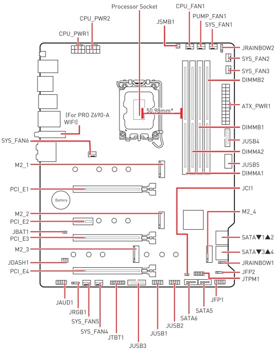
Collapse
How long does an MSD electron multiplier keep working? nine0107
The duration of the electron multiplier depends on many factors: the degree of loading of the MSD with analyses, the type of analytes, the analysis mode. Different manufacturers of different electronic multipliers indicate different durations of operation, while never giving exact numbers. A sign indicating the need for replacement is an increase in the voltage on the multiplier during automatic tuning to a value close to 2500V, or the impossibility of adjusting the detector gain. nine0003
Collapse
Why use a UPS? And why does it need to be connected to a ground line?
The
UPS is required to provide stable electrical power to the mass spectrometer. If the mains voltage fails or surges, the turbomolecular pump of the mass spectrometer or other expensive components may fail. The UPS should be connected to a grounded line in order to exclude phase mismatch of the voltage at the input of the mass spectrometer, to exclude failure of the power supply of the mass spectrometer. The power supply requirements at the workplace and the UPS connection diagram are given in the document: Requirements for the workplace of the gas chromatography-mass spectrometer.
nine0003
Collapse
Does the MSD require daily maintenance?
The MSD does not require daily maintenance. Basically, maintenance is required as technical problems arise.
Collapse
What kind of maintenance does the foreline pump require?
Foreline pump requires:
- periodic cleaning of the oil when a light foam appears, visible through the sight glass,
- adding oil if its level is below the minimum mark,
- change the oil if it turns dark.
The EDWARDS Foreline Pump Installation, Operation and Maintenance Manual, supplied with the equipment, contains a list and schedule of maintenance work with a detailed description of all work:
nine0003
| Types of work | Frequency |
|---|---|
| Oil level check | Monthly |
| Oil change | After 3000 hours of operation |
| Inspection and cleaning of the inlet filter | Once a year |
| Inspection and cleaning of gas ballast switch | Once a year |
| Cleaning the oil sight window | Once a year |
| Cleaning the housing and motor fan cover | Once a year |
| Partial pump overhaul | After 15,000 hours of operation |
| Replacing the evacuation plates | After 30,000 hours of operation |
| Motor check | After 15000 hours of operation
nine0203 |
Collapse
How long does one filament last?
The duration of the filament (in other words, the cathode or filament) depends on factors such as: intensity of use, compliance with the rules that prevent the oxidation of the filament, the characteristics of the analyzed substances, and others. On average, with daily use, one filament is enough for a period of 1-2 years. To prevent premature aging of the filament, it is necessary to turn off the filament while the solvent leaves the chromatographic column, and also avoid turning on the filament when air leaks into the vacuum chamber.
nine0003
Collapse
What are the most likely causes of MSD signal degradation or loss?
The reason for the deterioration or complete loss of the signal after some time of normal operation, most likely, is the contamination of the ion volume, lenses and curved prefilter. This also manifests itself in the inability to perform automatic detector tuning (gain calibration and mass resolution calibration). To eliminate this malfunction, it is necessary to clean the above parts according to the instructions given in the Operation Manual for the mass spectrometric detector. The intervals between cleanings range from several days to several months, depending on the intensity of use of the instrument and the purity of the samples.
