HILFE Zwei Stromkabel für CPU?
JavaScript ist deaktiviert. Für eine bessere Darstellung aktiviere bitte JavaScript in deinem Browser, bevor du fortfährst.
-
Ersteller
Rahmschnitzl -
Erstellt am
Rahmschnitzl
Neuling
-
-
#1
Hallo Zusammen,
ich bin gerade dabei mir einen neuen PC zusammen zu bauen und habe das erste mal auf ein vollmodulares Netzteil gesetzt (be quiet Straight Power 850W). Dort wird einmal ein 8 Pin Kabel und einmal ein 4+4 Pin Kabel zur Stromversorgung der CPU mitgeliefert. An meinem Mainboard (MSI Gaming Carbon Wifi) ist jedoch ein 8 + 4 Pin Anschluss verbaut. Nutze ich jetzt das 8 Pin Kabel und das 4 + 4 Pin Kabel gleichzeitig und benutze bei letzterem nur einen der 4 Pins? Damit laufen ja auch zwei Kabel von Netzteil zu CPU und iwie erschien mir das falsch. Kann mir jemand sagen, was ich hier tun muss?
(Hoffe das Thema gab es nicht schon, konnte es zumindest nirgends finden)
Vorab schon mal vielen Dank für eure Hilfe!
Wenn Du diese Anzeige nicht sehen willst, registriere Dich und/oder logge Dich ein.
Wenn Du diese Anzeige nicht sehen willst, registriere Dich und/oder logge Dich ein.
2k5lexi
Moderator Lars Christmas
-
#2
Schau Mal bei Geizhals oder im Handbuch des Mainboards wie die Anschlussbezeichnung ist. Dann schau im Handbuch des Netzteils welche Kabel das sind die du brauchst.
Eigentlich sollte alles beschriftet sein.
Aber ja, beide Buchsen mit Stecker belegen ist der Plan.
Ich meine dass die 8 Pin fürs Mainboard NICHT identisch sind mit dem 8pin für Grafikkarten. (Weiß ich aber nicht 100% sicher aus dem Kopf)
Da genau hinschauen!
Rahmschnitzl
Neuling
-
-
#3
Im Mainboard Handbuch steht beim 8 Pin Stecker CPU_PWR1 und beim 4 Pin Stecker CPU_PWR2. Im Netzteil-Handbuch steht zu den zwei 4- Pins beide 12V P4 Connectoren ergeben zusammen einen P-8 Connector und beim 8 Pin Anschluss logischerweise ein P-8 Connector.
Bei den Grafikkarten Kabeln habe ich keine Probleme, da steht klar VGA drauf und diese würde ich auch nicht verwenden, um die CPU mit Strom zu versorgen.
Patrickk87
Profi
-
-
#4
Ich habe auf meinem Maximus Hero Xi das gleiche , einen 8 Pin und einen 4 Pin. Ich nutze beide gleichzeitig. Funktionieren soll es auch nur mit einem 8pin , der zusätzliche 4 Pin ist eigentlich nur dafür da falls die CPU besonders viel Saft braucht im Falle von oc usw. Ich würde immer beide nutzen , sicher ist sicher .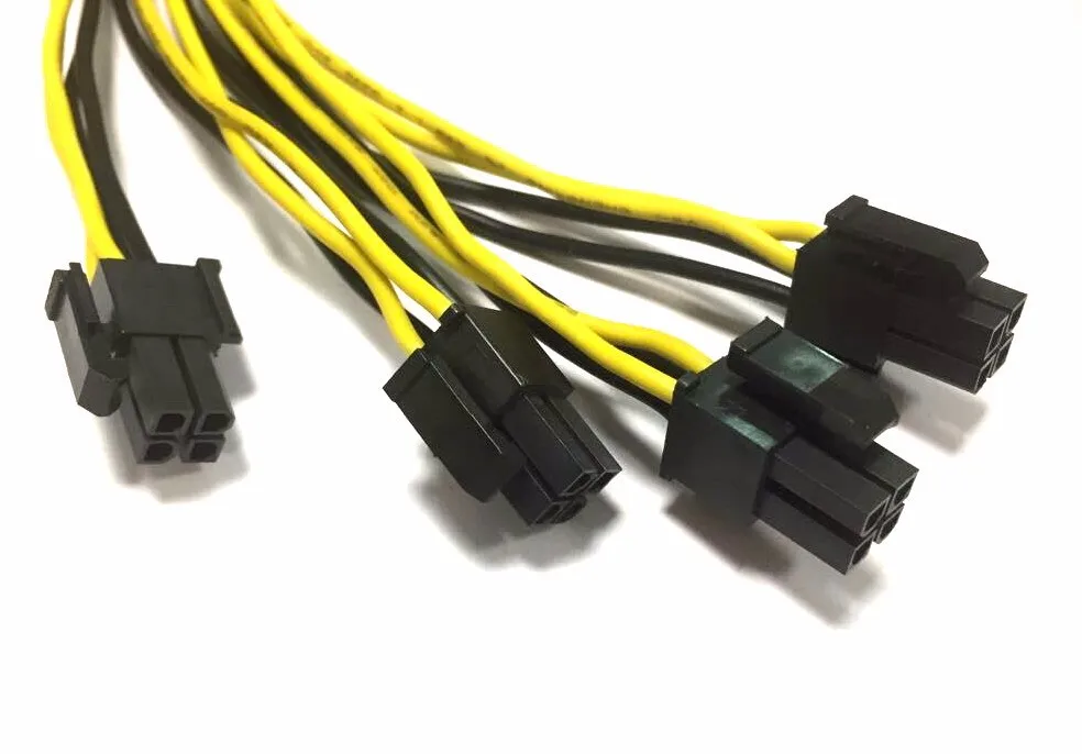
Rahmschnitzl
Neuling
-
-
#5
Also hast du zwei Kabel von Netzteil zu CPU gelegt? Einmal 8-Pin und und das 4 + 4 Pin wovon du dann nur noch einen 4 Pin zusätzlich angesteckt hast?
Erschien mir irgendwie so komisch, dass zwei separate Kabel die CPU versorgen sollen…
Sorry, dass ich nochmal so ganz genau nachfrage, ich hab nur etwas Schiss etwas kaputt zu machen, nachdem hier einiges Erspartes reingeflossen ist.
Infin1tum
Experte
-
#6
Der 8-pin alleine reicht völlig.
Rahmschnitzl
Neuling
-
-
#7
Weiß nicht, ob relevant, aber Prozessor ist der Ryzen 7 5800x…
Dann schließ ich einfach den 8 Pin an und lass das 4+4 Kabel in der Kiste.
Danke für eure Hilfe!
FM4E
Redakteur Golf-Fahrer
-
-
#8
2k5lexi schrieb:
Ich meine dass die 8 Pin fürs Mainboard NICHT identisch sind mit dem 8pin für Grafikkarten. (Weiß ich aber nicht 100% sicher aus dem Kopf)
Da genau hinschauen!Zum Vergrößern anklicken….
Dem ist auch so!
Patrickk87
Profi
-
-
#9
Rahmschnitzl schrieb:
Also hast du zwei Kabel von Netzteil zu CPU gelegt? Einmal 8-Pin und und das 4 + 4 Pin wovon du dann nur noch einen 4 Pin zusätzlich angesteckt hast?
Erschien mir irgendwie so komisch, dass zwei separate Kabel die CPU versorgen sollen.
Enthusiast
#10
Der zusätzliche 4 Pin (bei einigen auch 2. 8 Pin) ist für Extrem OC etc. Kann man weglassen. Steht aber auch im Handbuch
H_M_Murdock
Urgestein
#11
Normalweise ist es tatsächlich so dass der 8-Pin zwingend erforderlich ist, der zusätzliche 4-Pin soll bei extremen Bedingungen noch etwas mehr Strom liefern.

Nachdem mir am Rampage IV Formula schon ein 8 Pin geschmolzen ist (vermutlich schlechter Kontakt, die CPU hat «nur» 180 Watt gezogen was eigentlich Idee kein Thema sein sollte) werde ich zukünftig eher beide nutzen, sicher ist sicher.
Rahmschnitzl
Neuling
#12
Also ich habe jetzt doch auch beide angeschlossen und das System läuft wunderbar. Ich kann, wenn man beide hat, also auch nur beide Stecker empfehlen.
Vielen Dank für die Hilfe von euch allen!
FM4E
Redakteur Golf-Fahrer
#13
Wie bereits geschrieben wurde, reicht für den normalen Betrieb der 8-Pin-Stecker aus. Es schadet jedoch auch nicht, wenn du zusätzlich den 4-Pin-Stecker eingesteckt hast.
Anmelden, um zu antworten.
CPU Stromanschluss 2x 4Pin + 1 x 4 Pin + beep error
- marioca
- Mainboards
- Antworten
- 9
- Aufrufe
- 541
marioca
RTX 3090 und Anschluss an Straight Power 11 Netzteil 850 Watt
- wiesen’pfler
- Hilfe und Problemlösungen
23
- Antworten
- 85
- Aufrufe
- 4K
Techlogi
Frage zum CPU — Stromanschluss des Gigabyte Z690 Gaming X DDR4
- webbor1991
- Mainboards
- Antworten
- 1
- Aufrufe
- 2K
PC-Zusammenstellungs- und Aufrüstungs-Forum
- Antworten
- 1
- Aufrufe
- 389
blacklupus
MSI MPG Z690 EDGE WIFI DDR4 pipet 3x lang beim Einschalten
- meddie
- Mainboards
- Antworten
- 6
- Aufrufe
- 713
Teilen
LinkOben
UntenCPU vorübergehend mit 4- statt 8-pin betreiben? (Computer, Technik, PC)
Letzte Aktivität: 22.04.2022, 12:47
Details anzeigenPC Computer Technik Netzteil Technologie Spiele und Gaming Hallo,
ich hab meinen neuen PC gerade zusammengebaut:
- MSI B350 PC Mate
- AMD Ryzen 5 1600 CPU
- 2x 4 GB RAM G.
Skill 2800 MHz
- AMD R9 270X GPU
- WD HDD
- Samsung M.2 SSD
- Netzteil: Power LC600H-12
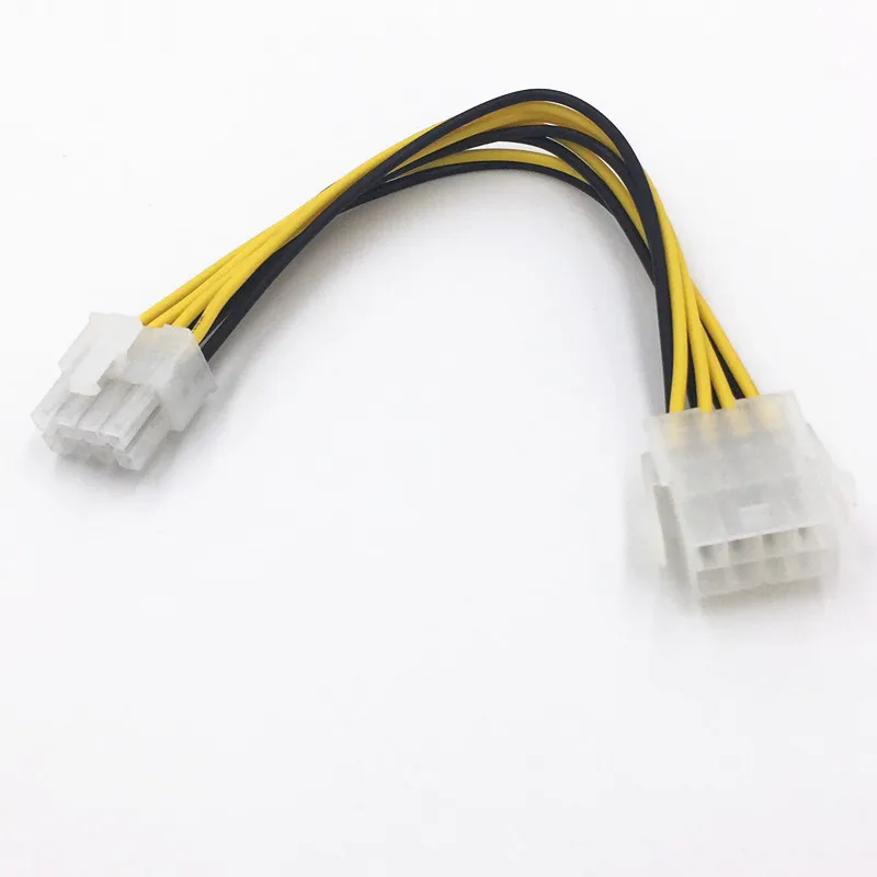
mein Problem: Das 8-pin-Kabel vom Netzteil reicht nicht bis oben zum 8-pin-Anschluss am Mainboard, das die CPU versorgt.
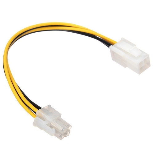
Mein alten Mainboard hatte nur einen 4-pin-Anschluss und war mit einem 4-pin-Verlängerungskabel an den 8-pin-Stecker gesteckt. Daher hab ich jetzt eine 4-pin-Verlängerung übrig.
Kann ich übergangsweise für die Installation des PCs ohne Gaming oder sonstige starke Beanspruchung guten Gewissens das 4-pin-Kabel am 8-pin-Stecker des Mainboards verwenden? Falls ja, wie genau muss ich die 4 Pins in die 8-Stecker stecken? Rechts, links, mittig?
Was ist der worst case? Kann dabei was kaputtgehen oder geht der PC im schlimmsten Fall einfach aus?
Ich hoffe sehr auf eure Hilfe. Ich will ungern jetzt am Sonntag die ganze Aktion abbrechen, wenn es nicht unbedingt nötig ist. Im Verlauf der Woche kaufe ich dann eine passende 8-pin-Verlängerung.

Viele Grüße =)
Vom Fragesteller als hilfreich ausgezeichnet
IBAxhascox
14.01.2018, 16:18
Kaputt gehen kann nichts wenn du das Kabel richtig anschteckst. Kann sein dass der PC gar nicht bootet oder er unter last einfach abstellt. Wie dus einstecken musst google ich kurz
4 Kommentare
4jort93
Community-Experte
PC, Computer, Technik
14.01.2018, 16:22
Hmm, wenn du stark übertaktest könnte sich das kabel erhitzen wenn der cpu sehr viel strom zieht. Weil bei halb so vielen kabeln ist der wiederstand doppelt so hoch, also entsteht doppelt soviel hitze.
Dann ist auch noch die oberfläche nur halb so groß. Also werden die kabel theoretisch 4 mal so warm. Und je wärmer die kabel werden desto höher wird noch mal der wiederstand.
Aber wenn du mal ein kabel angefasst hast, weist du das die sowieso nicht so warm werden. Von vielen grafikkarten wird sowieso mehr durch die kabel gezogen als es eigentlich sollte, würde mir nicht viele sorgen machen das das was passiert.
Solange der cpu nicht (stark) übertaktet wird sollte das von der power her auch locker ausreichen. Kann natürlich sein, dass das motherboard erkennt das der stecker fehlt und deshalb garnicht erst bootet aber wenn das system bootet glaube ich nicht dass du danach noch probleme hast.
Wernerrs
14.01.2018, 16:23
ich würde das lassen. wenn du falsch belegst — und dann ? es sei denn es paßt offensichtlich so rein und geht nur in einer position rein.
3 Kommentare
3Stahlbart2
14.01.2018, 16:27
das steht in der regel im handbuch des mainbaords
1 Kommentar
190,000 a tribute to fashion or a necessity? (added)
- Introduction
- Enermax Galaxy DXX 1000
- CoolerMaster Real Power Pro M1000
- OCZ PXS1000
- CoolerMaster Real Power Pro 1250
- Power Supply Test Procedure and Conclusions
The year 2008 is approaching, new 45nm processors have already been announced, triple SLI and CrossFire-X technologies are being prepared for release.
All these productive components require high-quality and reliable power supply. It is quite obvious that a home or office computer with one video card, a pair of hard drives and a mid-range processor does not require an expensive and powerful power supply. However, enthusiasts and professionals can use several quad-core CPUs, large disk arrays, tens of gigabytes of memory, and tandems of powerful video cards. For such configurations, there are power supplies of the upper price range, with a power of over 600W. Three models with kilowatt power from different manufacturers were provided for review. nine0017
For the first time, we got a power supply from Enermax, a company that has been developing and manufacturing its own switching power supplies, cases and other equipment since 1990. Almost all Enermax blocks are based on their own design. Let’s take a closer look at the oldest power supply, from the Galaxy DXX 1000 series, with a maximum power of 1 kW, which follows from the name of the model.
The unit comes in a fairly large box without any carrying handles. The sides of the box colorfully depict a large number of possible consumers that can be powered by the Galaxy DXX. Here and four-socket quad-core processors, and 5 video cards, and 24 hard drives. Impressive, even hard to believe in it. nine0017
After removing the entire package from the box, we see a rather impressive spectacle of paper instructions and booklets, the unit itself weighing 4 kilograms and a mass of wires with adapters. The case has increased dimensions, 150 x 86 x 220mm (W x H x D).
recommendations
The model provided for review is called EGX1000EWL, the maximum current through the +12V line reaches 75 amperes, and in severe ambient temperatures up to +50°C. Looking ahead, we note that this power supply has two really separate + 12V branches. Due to the presence of active PFC, the source can operate both in 220V and 110V networks.
Installed two fans effectively blow through the interior of the power supply. nine0017
Entire non-removable power connectors are sufficient to power any typical home computer. In addition to the main motherboard power cords, two video cards, two processor (!) cables and three interface connectors (SATA and PATA), there is an 80mm fan tachometer output. The +12V power wires are marked AWG16, which means thicker wire than most other units.
In addition, the rear panel has connectors for connecting additional cables: two red ones for video cards and six peripheral ones. It will not be possible to connect cables from video cards to peripheral connectors incorrectly, since the latter have one hole plugged. However, there is no protection against the possibility of connecting a peripheral cable to the red connector, except for the color marking and a slightly greater distance from the other connectors. If the cables are mixed up, an emergency shutdown will occur without irreparable consequences for the components.
The connection of the cables to the block is quite rigid, and considerable force is required to ensure contact. nine0017
The cables coming out of the power supply are securely fixed with cable ties, there is a plastic ring to prevent chafing of the insulation. All cords have a black and yellow sheath that goes inside the case, it’s nice to know that the manufacturer did not save on penny components.
There are five video card connectors, two of which have clip-on pins required by the PCI-Express 2.0 standard. In addition, there is an adapter for «turning» one 8-pin processor power cable into a PCI-Express 2.0 connector, also 8-pin. There is nothing tricky in this adapter, both cables are mechanically the same MiniFit-8, however, the contacts of the + 12V line and the ground are mirrored. nine0017
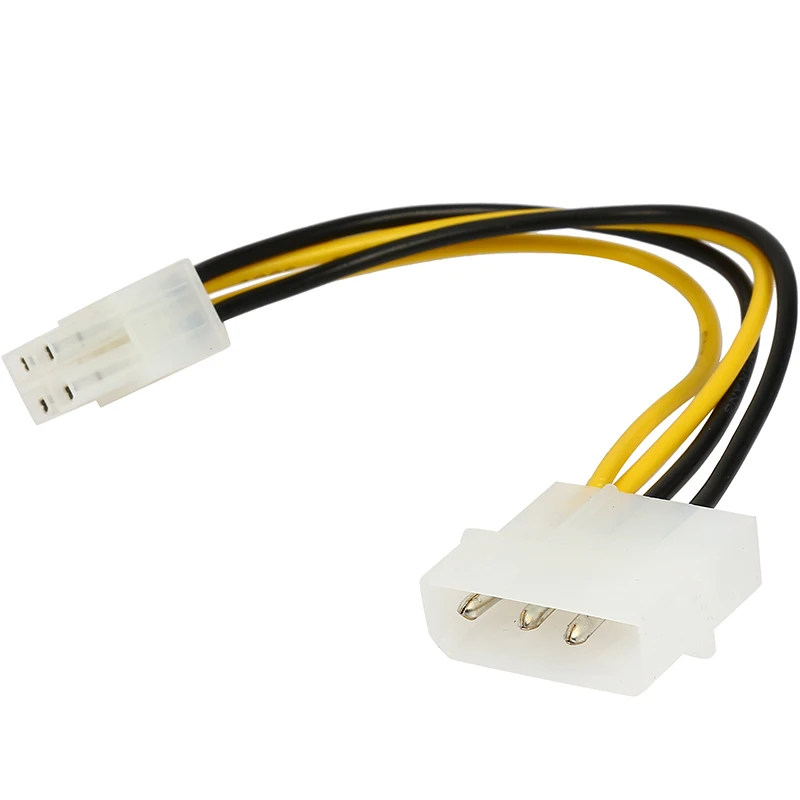
In addition, there is a 24-pin adapter for the motherboard, with a separate +12V channel connection.
Included with the power supply is a brochure describing the functions of this adapter in English and German. It states that some motherboards, such as Gigabyte GA-P35-DQ6, MSI P35-Platinum, may have higher power consumption requirements. If the user encounters problems when switching on, this adapter must be used. To do this, you need to connect the motherboard to the Enermax Galaxy DXX using this adapter, and connect a regular peripheral connector to the 4-pin +12V connector. Separately, it is indicated that in this case it is NOT necessary to connect a special 4-pin + 12V connector for the motherboard. nine0017
A 4-pin auxiliary cable with two +12V lines is available for server boards.
If you list all available connectors and their length in a table, you get an impressive list. The Enermax Galaxy DXX 1000 would definitely win the «Most ATX PSU Cables» contest if there was one.
On the rear panel, in addition to the usual network connector and the illuminated off button, there is a red button
self-destruction
disabling the alarm and resetting the protection circuit.The status is indicated by a two-color LED. The normal state of the switched on unit is green, in case of an accident or standby mode, the LED changes color to red. Additionally, the protection operation, for example, the stop of the fan impeller, is accompanied by a loud squeak from the speaker built into the unit. nine0017
Let’s take a look at the internals by opening the housing cover.
The double-sided PCB houses several transformers, two anodized aluminum heatsinks to dissipate heat from key components, several smaller daughterboards, and a host of passives and filter capacitors. Next to the two large transformers in the center there is a smaller one to provide +5V standby voltage. nine0017
The APFC controller is based on the Texas Instruments UCC3817 integrated circuit, and the installation is surprisingly messy, some SMD components are very skewed relative to their seats.
We hope this is a shortcoming of the specifically tested power supply, and not the general quality of all representatives of this line. The power switches in the PFC circuit are four MOSFET 24N50, each of which is rated for power up to 300W.
A pair of heavy duty assemblies are used as the mains rectifier bridge
RS2005G
, in parallel connection. nine0017
APFC is followed by high voltage converters based on two independent PWM controllers
UC3842
. Each of the controllers controls two 2SK2607 field-effect transistors, which transfer power to each of the transformers. One transformer is used to create voltage +12V (marked as “CPU”, with virtual separation into two additional lines) and +5V, +3.3V is generated on the basis of the second one along with three more virtual +12V channels. As a result, two real independent +12V circuits are divided into 5 lines with current protection on each. Note that the protection operates at a current value of about 24-26A, which exceeds the safety requirements of the IEC EN-609 standard.50. Recall that this standard prescribes: «the maximum power of a short-circuited circuit on any of the outputs should not exceed 240VA.» In terms of the +12V line, the maximum current should not exceed 20 A. Each of the power MOSFETs has ferrite beads on the terminals, which helps to reduce the level of high-frequency noise.
The use of this two-transformer connection reduces the interference of noise from peripherals and noise from processors. Low voltage lines are also significantly less subject to maximum current dependency. To smooth the channel + 5V and + 3.3V, there are two assemblies of Schottky diodes
40CPQ045
, each of which is designed for current up to 40A. Channels + 12V have higher voltage 40CPQ060, a pair for both channels. For standby voltage + 5VSB, a separate transformer and Schottky diode F20SC6 (20A, 6V) are used. Negative voltage -12V for the motherboard is traditionally created using a linear regulator circuit 7912. All Schottky diodes also have ferrite beads.Unfortunately, due to the dense mounting, it was not possible to take a photo of the low-voltage circuits.
Cooling is provided by 135mm and 80mm fans. A large fan blows air into the PSU case, while a smaller one mounted on the rear panel blows hot air out of the system unit. When the system is turned on, both fans spin up to the maximum, then immediately reduce the speed to the minimum required for cooling. The power supply heat sinks have fixed thermal sensors, according to which the fan control circuit regulates the rotation speed. Fan markings: Silence RL4T B1352512MB-3M and Superred CHA8012DB-OA(E). The 135-mm model has transparent blades, but no backlight, although there are holes for four LEDs in the frame-case. nine0017
Both fans have impeller suspension on ball bearings, and the noise from the operation of the unit is audible, but not intrusive and does not interfere with operation under normal conditions of use. A few days later, the main 135mm fan made itself felt in the form of a slight rumble of bearings, which is not fatal, but unpleasant.
The modular board with connectors is connected to the unit with a thick wire with a conductor diameter of 4mm. nine0017
The 8-bit microprocessor SONIX SN8P2602, installed on the daughter board with a speaker, monitors the operation of the power supply and all its components.
As expected from a kilowatt power supply, the manufacturer did not skimp on either the design of the unit or the choice of components. Therefore, the moment with the poor quality of soldering and installation is doubly incomprehensible and unpleasant. Enermax commented on our remark. The low quality of the installation is due to the need to manually upgrade the existing EGA1000EWL and EGA850EWL blocks, which did not have 8-pin power connectors for video cards. The upgrade consisted of installing a new cable, reinforced 12V channels from 18A to 24A, to support powerful video cards, in connection with which some components on the boards were replaced.