ATX (and PCI-E) Power Supply Connector Guide
ATX and PCI-E sockets can be a bit of a mine-field, there are various sizes and some thateven look the same from a distance but have subtle differences (PCI-E 6+2 and ATX 8/4+4 I’m looking at you).
Anyway, I have attempted to simplify for you, find the picture of the plug you want to connect to, read about the sockets you can use. Can’t get easier than that.
Be sure to check the bottom of the page for an extra note about the pin styles and pitches on the PCB side, there are two different variants (at least of the Chinese produced sockets) which take the same plug, but have different pitch at the PCB, fun times huh!
ATX 20 Pin Motherboard
Socket: ATX 20 Pin
Alternative: ATX 24 Pin (4 unused pins)
|
|
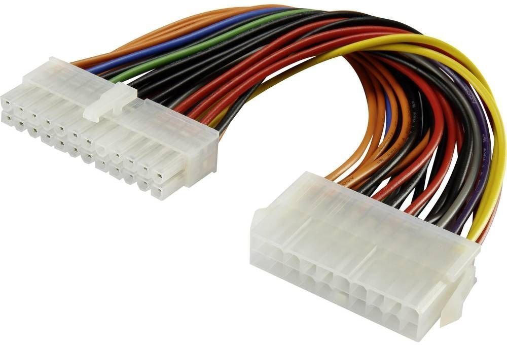
ATX 24 Pin Motherboard
Socket: ATX 24 Pin
|
|
ATX 20+4 Pin Motherboard
Socket: ATX 24 Pin
Note: The “+4Pin” is a different keying to a normal “4 Pin”.
|
|
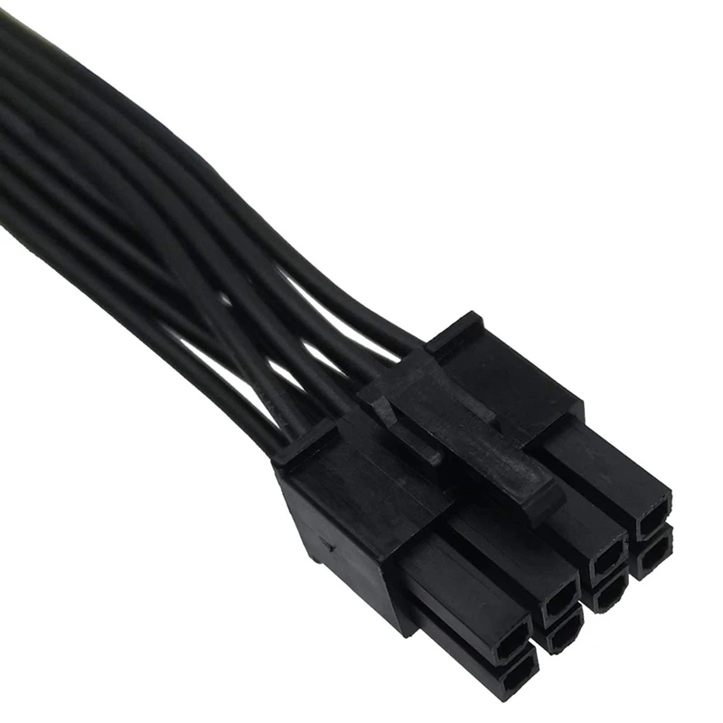
ATX 8 Pin (4x 12v, 4x Gnd) Motherboard Extra CPU Power
Socket: ATX 8 Pin
Note: Take note, this is different to the 8 pin (or 6+2) PCI-E power plug which has 3x 12v and 5x Gnd. You can easily tell the difference, 4x Yellow wires = this one, 3x Yellow wires = PCI-E.
|
|
ATX 4+4 Pin (4x 12v, 4x Gnd) Motherboard Extra CPU Power
Socket: ATX 8 Pin
Alternative: Two ATX 4 Pin sockets, with some space between them.
|
|
ATX 4 Pin (2x 12v, 2x Gnd) Motherboard Extra CPU Power
Socket: ATX 4 Pin
Alternative: 6 Pin PCI-E
|
|
PCI Express 6 Pin Power (3x 12v, 3x Gnd)
Socket: 6 Pin PCI-E
|
|
PCI Express 6+2 Pin Power (3x 12v, 3x Gnd, 2x Gnd)
Socket: 6 Pin PCI-E
Note: Obviously using a 6 pin PCI-E socket you can’t connect the +2.
|
 You can NOT use an 8 pin ATX socket to mate a 6+2 as the keying is different. 8 Pin PCI-e sockets are hard to find. It’s only two extra grounds so I really don’t see the point of them, just leave it hanging.
PCB Pin Pitches/Styles for Chinese Produced ATX/PCI-E Sockets
At least the vertical sockets for the plugs above I have seen come in two different pitches/styles out of China at the PCB side (the “plug side” of the socket is the same for both and fits the plugs on a typical ATX Power Supply).
There is the “5569” Chinese part number style with a solid 1mm square pin and this has a 4.2mm pitch in both X and Y direction.
Then there is the “5566” Chinese part number style with a pointy flat pin and this has a 4.2mm pitch along the rows (so the long direction) but a 5.5mm pitch between the rows (short direction).
See the diagram below, the plug side is the same for both, but you can see the PCB side has a different pitch.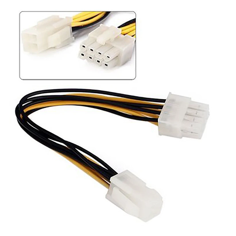
ATX12VO Operation, Connectors and Pinouts
Home | Handbook | Tutorial | Topologies | SMPS design | Thermal design | Software | PCB design | Computer PSU | UPS | Circuit | Transformers | Formulas | EE Reference | Inverters | Generators | Solar
WHAT IS ATX12VO?
ATX12VO is a single rail power supply standard developed by Intel. This standard eliminates 5V and 3.3V rails from desktop power supply leaving only 12V power and 12V standby. All other voltages requires for the processor and other PC components will have to be produced on the motherboard. Such architecture reduces the size and cost of the PSU and increases its efficiency. The size and cost are obviously reduced by eliminating additional outputs and simplifying transformer design. The efficiency is increased because higher voltage output generally has lower losses than lower voltage ones. This single rail approach was actually proposed by Google in 2006 white paper, but it took more than a decade until Intel came up with such specification.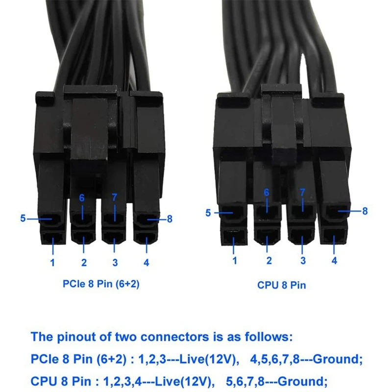 Note that ATX12VO platform does not necessarily reduce the overall cost and power consumption of the computer because additional power conversion is just shifted from PSU to the motherboard.
POWER CONNECTORS AND
PINOUTS
The main power connector for motherboard is 10-pin Mini-Fit Jr style, part number CP-01110031-X2 (CP01376S). The pinout diagram shows the front (i.e. pin-side) view. The colors represent recommended colors of the wires. There is no guarantee of course, that the manufacturers won’t use other colors. Note that the diagram in Intel’s design guide shows back view (i.e. from wires side). The pins for this header are rated at 9A maximum. Assuming some derating (8A/pin), such header can provide 288 watt. This is sufficient for most ATX and its derivatives (like SFX and TFX). Optional remote sensing allows to compensate for voltage drop on +12V cable wires by taking feedback from motherboard rather than from PSU board. However, if remote sense is used, only two power pins are left for the main rail.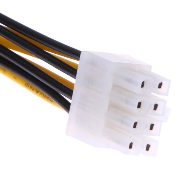 In this case, the cable can provide 192W (again, assuming 8A/pin).
If motherboard requires more wattage than the main cable can provide, the spec allows for additional connectors.
Extra board 6-pin connector 12V1 and CPU connector 12V2 are the same as in ATX2 systems. Additional power can be provided from 8-pin power connector 12V2 (see pinout diagram). It is sometimes called EPS connector because it was used in EPS server power supplies.
The Intel spec notes that CPU 12V2 rail should have a separate current limit to meet the requirements of EN 60950 and UL 60950. This is not new- there was always such requirement. In practice, as far as I know, most PSU manufacturers implement a combined current limit for all 12V rails. Separate current limit would require a separate regulator on 12V2, which would mean higher cost and extra complexity.
PCI EXPRESS CONNECTORS
The ATX12VO standard allows 6-pin or 8-pin connectors for PCI Express graphic expansion cards (sometimes called PEG).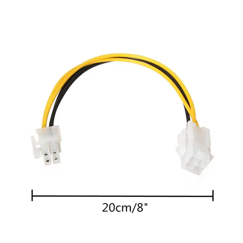 Old video cards have connectors with 6-pin. The newer ones per PCI Express specification 2.0 have 8 pins. Therefore many power supplies provide so-called 6+2 PCI-E cable, which works with both types. The 6+2 part has a detachable 2-pin piece that you can leave unplugged for the 6-pin card- see the diagram to the right. Note that 8-pin PCI-E connector looks similar to 8-pin extra power connector, but their pin designations are different and they should not be mixed up. PCI headers are usually labelled as such.
See also connectors and pinouts for ATX12V and for some brand name desktop computers.
How to connect the motherboard to the power supply
In our detailed instructions, we will look at how to connect the motherboard to the power supply. This is the hardware that powers everything inside the computer and many of the peripherals outside of it. It determines how many devices you can install and how efficiently the whole system can work.
When installing a new PSU, there are a few subtle features to pay attention to. For starters, there’s the 12V rail, usually referred to as +12V in datasheets, which is the bit that powers most components, most notably the graphics card and processor. The specification should state the maximum capacity of each 12-port rail. In good devices, there are several of them, with one bus dedicated to the processor, while the rest will provide power to other components.
Wiring and more
The PSU should ideally have all the necessary connections that are dedicated to the components. They are built to a specification based on the ATX standard, the latest version is currently up to v2.3, although nothing has changed since v2.2 regarding connectivity.
High-end Intel motherboards often require an 8-pin ATX12V connector called EPS12V. In addition, you’ll need standard 4-pin Molex connectors for common internal peripherals, Serial ATA for hard drives; for high-performance graphics cards, 6-pin or 8-pin PCI Express power connectors are sufficient. Serial ATA and PCI Express adapters are also available to allow the use of older Molex connectors.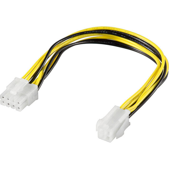
What you need to know before you buy
While PC case styles can vary greatly in appearance, their internal dimensions must conform to the ATX specification. This means they must accept PSUs that are 15×9 cm and at least 14 cm long. Of course, there are exceptions to this rule: firstly, mini cases can use smaller PSUs that comply with the microATX standard, or PSUs that are fully developed custom-made where the physical size differs from this standard. Be sure to check before buying.
How to determine the required power
Make sure you have selected a sufficiently powerful power supply. As a rough guide, you need to add the usable power—sometimes referred to as TDP—for the CPU and graphics card. These are the two main sources, and it’s important that the 12V rail on your new hardware provides enough power.
Mounting
The standard ATX mounting points are the same. In some cases, you may need to remove the CPU cooler or case top to gain full access.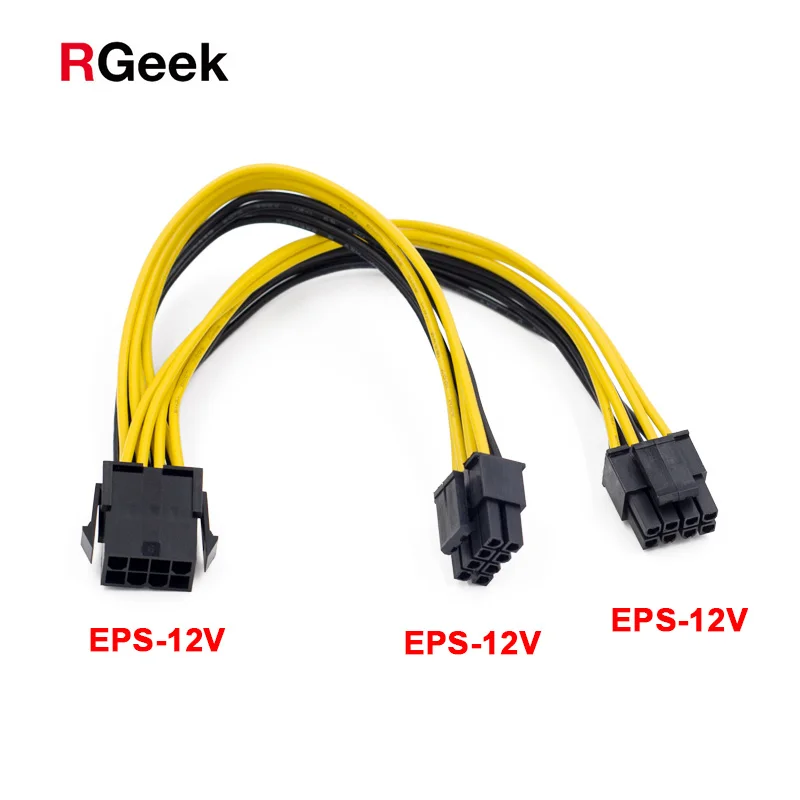 For the tower form factor, it’s usually easiest to lay the case on its side. Fasten the PSU with four standard screws. Make sure you can see all four screws, as the hardware can be rotated incorrectly.
ATX Power
This is a 20/24 pin ATX motherboard power connector, older systems only use the first 20 pin. In this case, the additional 4 pins can simply be disconnected.
ATX12V Power
The strangely named ATX12V plug is specially designed for the CPU and must be powered by its own 12V rail. Intel boards — mainly 1366 socket models — require an improved 8-pin version. So check the equipment before buying.
PCI Express
6-pin and 8-pin PCI Express connectors are only required for medium and high-end graphics cards. Depending on the model, the card may require one or two 6-pins, or one 6-pin and one 8-pin. If you plan to use two graphics cards, then this will obviously double!
Molex and SATA
The remaining connectors are usually used for any optical drives and hard drives in the system, mostly old 4-pin Molex.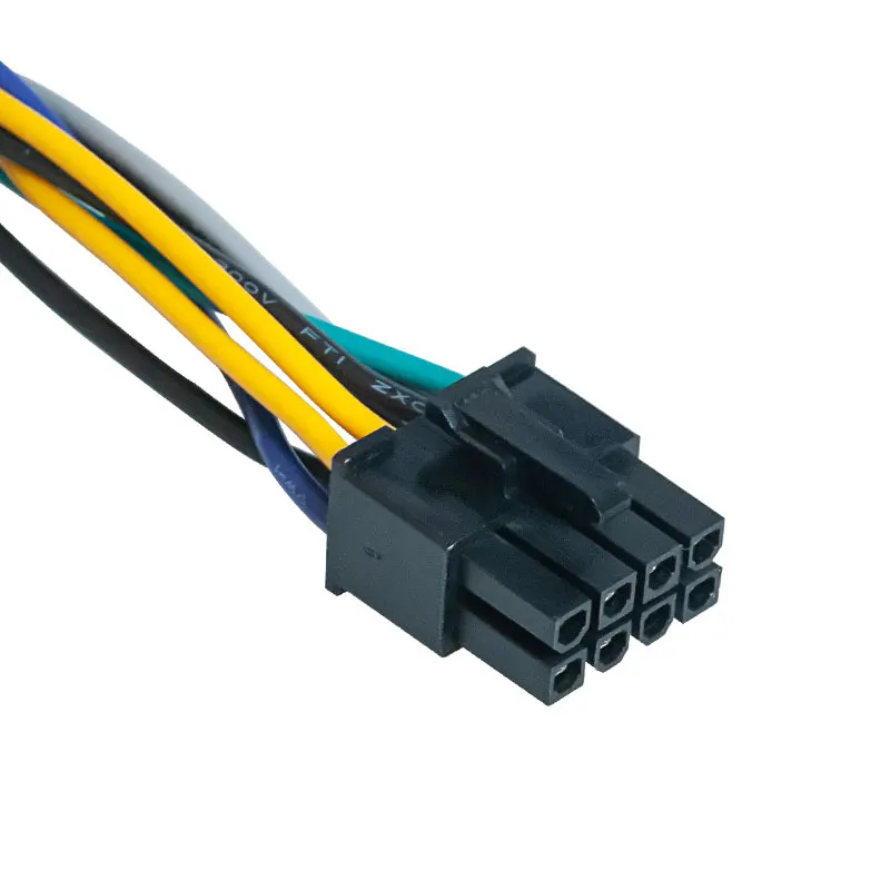 SATA hard drives are the latest exception requiring SATA.
Adapters
As requirements have increased or changed over the years, instead of making old PSUs redundant, companies simply offer adapters. They connect to one or two Molex and turn them into SATA, PCIe 6-pin and PCIe 8-pin.
Cables inside the case obstruct airflow and can cause the system to get hotter than it should. It’s always worth taking a little time to wrap, tuck and tie cables for a neat finish.
ATX 6-pin motherboard power connector
The 6-pin ATX power connector is a motherboard power connector used to provide +12VDC.
This 6-pin connector is also sometimes used to provide additional power for high-performance graphics cards.
On motherboards, the more common connector used for this purpose is the ATX 4 pin power connector, which is used either alone or with a second 4-pin connector, making an 8-pin connector.
The terms «PCI Express cables» or «PEG cables» (for PCI Express Graphics) are sometimes used to describe the 6-pin 12V power connector.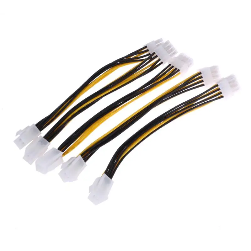
ATX 6-pin 12V Power Connector (ATX v2.2)
Below shows the pinout for the standard 12-pin ATX 6 (3×2) power connector with version 2.2 of the ATX specification (PDF).
Notes: If you are using this pinout to check supply voltage, remember that the voltages must be within the specified ATX tolerances. 93 + 12VDC
ATX power supply.
Using the 12-pin ATX 12-pin power connector
The 6-pin 12V power connector is used to power PCI Express expansion cards that require more power than their expansion slots can provide (which is 75W.
Some graphics cards, for example, draw more than 75W, in which case connecting a 6-pin 12V power cable can provide more power to the card.
Graphics cards are sometimes shipped with an 8-pin connector if they can use more power than what a 6-pin cable can provide.